Welcome to 6WD expansion board manual repository
6WD expansion board manual
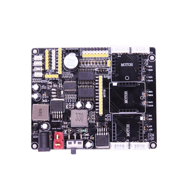
Front:

Back:

1. 5V/3.3V Power supply

1-1 Position
Here you can switch the voltage supply of 5V and 3.3V. If the jumper cap is used to connect the left two pin headers, it is 5V power supply; if the right two pin headers are connected, it is 3.3V power supply.
2. Bluetooth module interface

2-1 Position

2-2 Schematic diagram
The interface has four pins: VCC, GND, TX, RX. VCC is 5V under normal operating conditions.
3. Buzzer

3-1 Position

3-2 Schematic diagram
Active buzzer is used here.
4. Servo interface

4-1 Position

4-2 Schematic diagram
The expansion board uses the IIC external drive chip PCA9685 to control the servo, which can support independent control of the 8 channels servo.
5. Motor interface with speed dial

5-1 Position


5-2 Schematic diagram
The expansion board has 4 motor interfaces with speed dials, each of which can measure speed, control, speed and stop separately.
6. Motor driver module interface

6-1 Position


6-2 Schematic diagram
The motor drive module needs to be plugged in. (Buy this expansion board, we will give 3 matching motor drive modules)
Note: The driver module should be installed in the correct orientation to work properly (as shown in Figure 6-4).
The motor interfaces j1, j2, j3, j4, j5, and j6 are on the back of the expansion board.


6-3 Front and back of motor drive module

6-4 Driver module installation position
7. Power switch

7-1 Position
It is used to control the expansion board power switch.
8. T-type power supply interface

8-1 Position
Connecting the battery that matches the interface could supply power for the expansion board. The expansion board supply voltage must not exceed 12.6v.
9. Camera interface

9-1 Position

9-2 Schematic diagram
The interface has four pins: VCC, GND, RX, TX. Serial port communication mode can be used to connect a serial port camera with WIFI function.