System Delay
System Delay1. Learning ObjectivesPrinciple of Tick TimerThe role of delay2. Hardware Construction3. Experimental steps1. Open the SYSCONFIG configuration tool2. Tick timer configuration3. Write the program4. Compile4. Program Analysis5. Experimental phenomenon
1. Learning Objectives
- Learn the basic use of the pins of the MSPM0G3507 motherboard.
- Understand the usage of the tick timer.
Principle of Tick Timer
The tick timer is a commonly used hardware timer used to generate fixed-cycle interrupts or trigger timing operations. Its basic working principle is to count the main clock (MCLK) to achieve precise time intervals.
The SysTick timer is a standard timer built into the Cortex-M0 processor. As a 24-bit down counter, it has an automatic reload function and can mask system interrupts. All controllers based on the M0 core are equipped with a SysTick timer, which makes it easier to port programs between different devices. The SysTick timer is usually used in the operating system to provide the necessary clock beats for task scheduling, play the role of a "heartbeat", and ensure that the system executes tasks on time. Since all M0 core chips contain SysTick timers, the program does not need to reconfigure the timer during porting, and the porting difficulty is lower than that of ordinary timers.
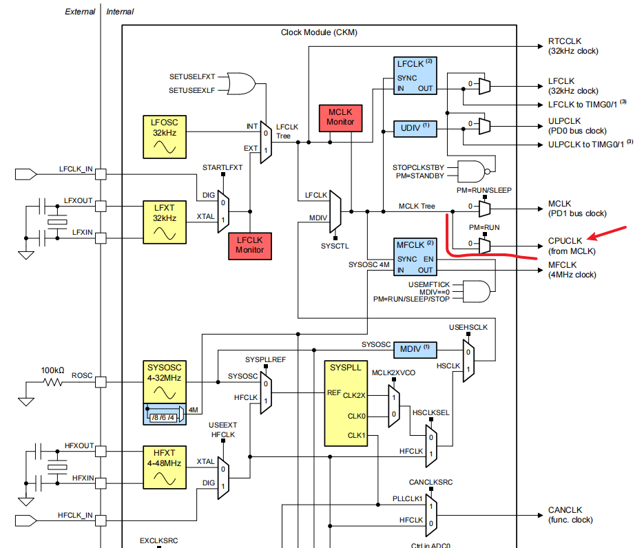
In the system clock configuration, RCU provides the external clock of the Cortex system timer (SysTick) through MCLK. By default, the frequency of MCLK is 32MHz. By setting the SysTick control and status registers, the timer status can be controlled or read. For detailed information about the system clock, please refer to the clock tree section in the user manual.
Clock tree:
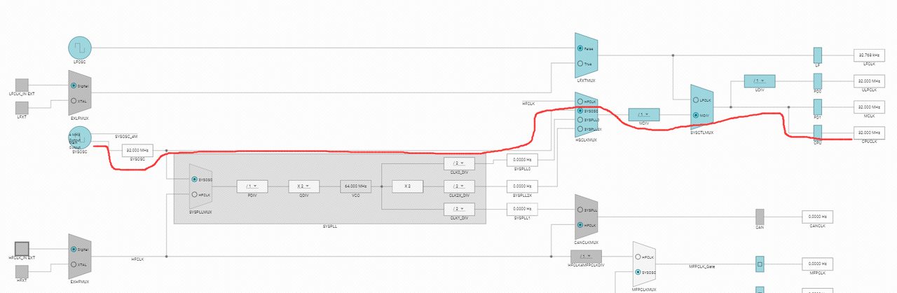
Default clock path in the project:
The working mode of the SysTick timer is: after setting the initial value and enabling, the count value decreases by 1 every time a system clock cycle passes. When the counter reaches 0, SysTick will automatically reload the initial value and continue counting, and set the internal COUNTFLAG flag to 1, triggering an interrupt (provided that the interrupt is enabled).
The role of delay
The delay function is a function used to introduce artificial delay in the program. Its main function is to suspend the program execution within a specified time period. In simple terms, the role of the delay function is to wait, which actually means waiting for a period of time before executing the next code.
- Hardware response waiting: Many hardware devices require a certain amount of time to complete operations or stabilize. For example, after sending an initialization command to a display screen, if you start sending display data immediately, display anomalies may occur. Delay can give the hardware enough time to complete initialization and ensure normal operation.
- Timed task implementation: Delay can help implement operations at fixed time intervals. For example, an automatic door controlled by a microcontroller checks every 5 seconds whether the infrared sensor detects an obstacle. If not detected, the door remains closed; if detected, the door opens and remains for 2 seconds before automatically closing.
- User interaction optimization: In user interaction scenarios, delay can achieve a better experience. For example, when a button is pressed, the "anti-shake" function is realized through delay to avoid multiple triggers caused by mechanical vibration. In addition, in the switching of the status indicator light, the delay is used to control the frequency of on and off, making the light flashing smoother and easier to observe.
2. Hardware Construction
This course does not require additional hardware equipment, and can directly use the onboard LED lights on the MSPM0G3507 motherboard. In the previous course, we used inaccurate delay. This course uses tick timer to achieve accurate delay.
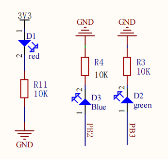
We set up two LED user lights on the motherboard, and users can DIY their functions. The following takes LED1 as an example.
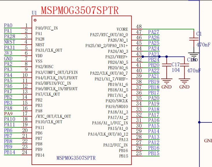
MSPM0G3507 main control diagram
LED part schematic diagram
3. Experimental steps
1. Open the SYSCONFIG configuration tool
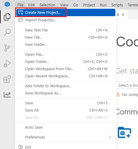
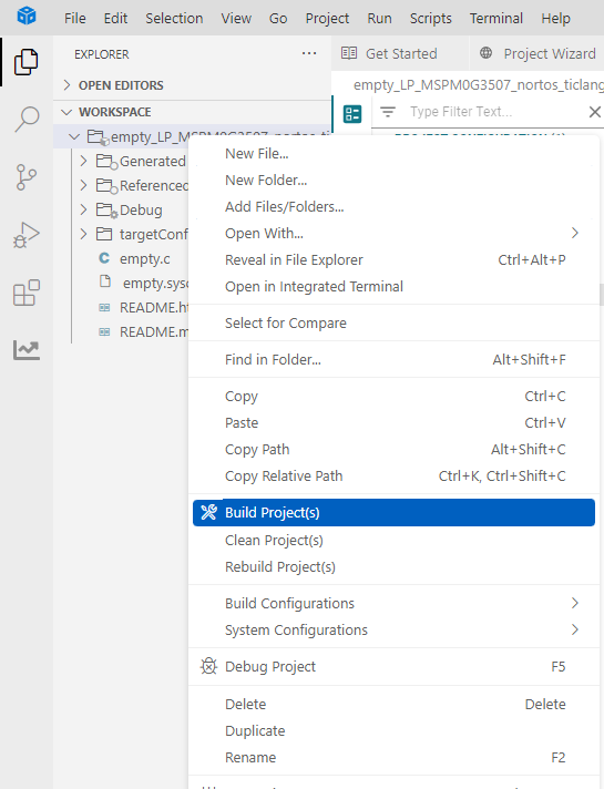
Create a blank project empty in CCS.

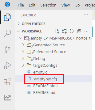
Find and open the empty.syscfg file in the left workspace of CCS.
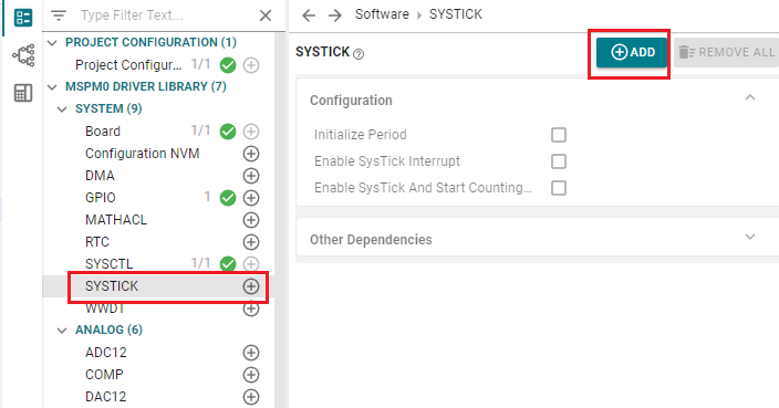
In SYSCONFIG, select MCU peripherals on the left, find the SYSTICK option and click to enter. Click ADD in SYSTICK to add a tick timer.
2. Tick timer configuration
The tick timer uses MCLK for timing, and MCLK is 32MHz, which means that the time it takes to count once is 1÷32,000,000 = 0.00000003125 S. Assuming that we set the value to be counted to 32000, the time it takes to count 32000 numbers is: 32000 x 0.00000003125 = 0.001 S = 1MS. So if we want to set a 1ms tick timer, we set the count value of the tick timer to 32000.
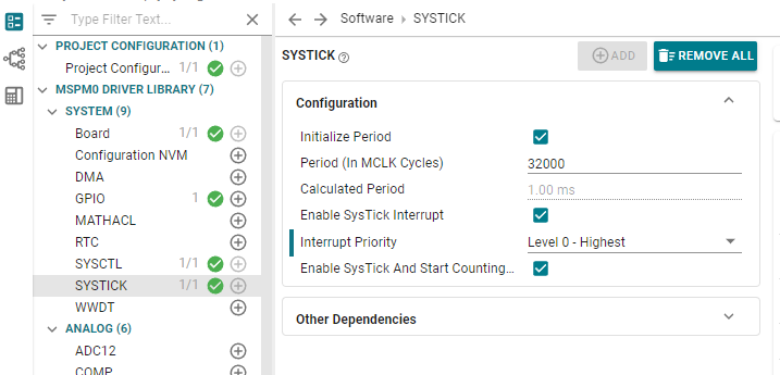
Parameter Description:
Initialize Period: Initial timer period.
Period (ln McLk Cycles): Set the period count value, here we set it to 32000.
Calculated Period: The time spent counting. The software will automatically calculate this value.
Enable SysTick Interrupt: Whether to enable the tick timer interrupt.
Interrupt Priority: Select the interrupt priority. Here the highest priority interrupt is selected.
Enable SysTick And start Counting: Whether to enable the tick timer and start counting.
Use the shortcut key Ctrl+S to save the configuration in the .syscfg file.
Compile after saving
3. Write the program
After configuring the tick timer, we also need to manually write the interrupt service function of the tick timer. Because we have enabled the interrupt of the tick timer, when the count value of the tick timer decreases from the set initial value to 0, an interrupt will be triggered, and the interrupt service function will be automatically executed after the trigger. The name of the interrupt service function corresponding to each interrupt is usually fixed and cannot be modified at will, otherwise the interrupt service function will not be entered correctly. The name of the interrupt service function is SysTick_Handler
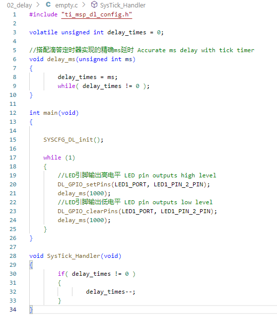
In the empty.c file, write the following code
x#include "ti_msp_dl_config.h"volatile unsigned int delay_times = 0;//搭配滴答定时器实现的精确ms延时 Accurate ms delay with tick timervoid delay_ms(unsigned int ms){ delay_times = ms; while( delay_times != 0 );}int main(void){ SYSCFG_DL_init(); while (1) { //LED引脚输出高电平 LED pin outputs high level DL_GPIO_setPins(LED1_PORT, LED1_PIN_2_PIN); delay_ms(1000); //LED引脚输出低电平 LED pin outputs low level DL_GPIO_clearPins(LED1_PORT, LED1_PIN_2_PIN); delay_ms(1000); }}void SysTick_Handler(void){ if( delay_times != 0 ) { delay_times--; }}4. Compile
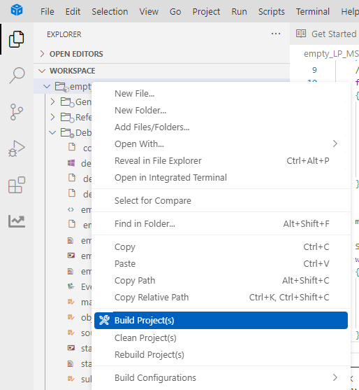
If the compilation is successful, you can download the program to the development board.
4. Program Analysis
- empty.c
Define a global variable delay_times to record the remaining milliseconds of the delay.
delay_ms(): Implements precise millisecond-level delay.
main(): After initializing the system, call DL_GPIO_setPins to specify the pin output high and low levels to control the LED light on and off.
SysTick_Handler(): decrement delay_times in the interrupt. If delay_times is non-zero, decrement it by 1 each time the interrupt occurs. When it is decremented to 0, the delay is completed and the while loop in delay_ms() exits.
5. Experimental phenomenon
After the program is downloaded, you can see that the LED1 light on the MSPM0 development board turns on for 1s and off for 1s, repeating the cycle.