Mecanum Wheel Movement Principle
Mecanum Wheel Movement PrincipleStructure of Mecanum WheelMotion state analysisMecanum wheel analysisWheel AWheel BAnalysis of the motion state of the carMotion decompositionForward/BackwardLeft/Right PanFront/Back PanRotate in PlaceStopNotes
The Mecanum Wheel is a specially designed wheel, which is mostly used in scientific research, teaching, robot competitions and other scenarios. Its movement mode is very cool, including forward movement, lateral movement, oblique movement, rotation and their combination.
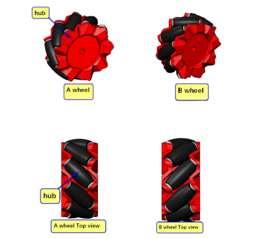
Structure of Mecanum Wheel
The Mecanum Wheel (hereinafter referred to as the Mecanum Wheel) is composed of a hub and a roller around the hub. The roller is a small driven roller without power. The angle between the axis of the Mecanum Wheel roller and the axis of the hub is 45 degrees, and there are two types of wheels A and B that are mirror images of each other, or they are called left-handed wheels and right-handed wheels.
Motion state analysis
Mecanum wheel analysis
Take the front of the trolley as the positive direction, and agree that the direction of the wheel moving forward is the motor forward rotation, and the direction of the wheel moving backward is the motor reverse rotation.
xxxxxxxxxxThe rollers on the outer periphery of the Mecanum wheel are in contact with the ground. When the Mecanum wheel rotates around the hub shaft, the rollers will generate friction with the ground. We can decompose the ground friction along the directions perpendicular and parallel to the roller axis.Among them, the component perpendicular to the roller axis belongs to rolling friction, which causes the roller to rotate and is an invalid motion;The component parallel to the roller axis belongs to static friction, which causes the roller to move relative to the ground, thereby driving the entire Mecanum wheel to move along the roller axis.
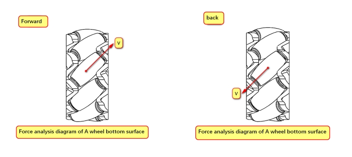
Wheel A
xxxxxxxxxxThe actual direction of movement needs to be determined based on the part of the wheel that contacts the ground
Forward: The actual movement is diagonally to the right front
Backward: The actual movement is diagonally to the left rear
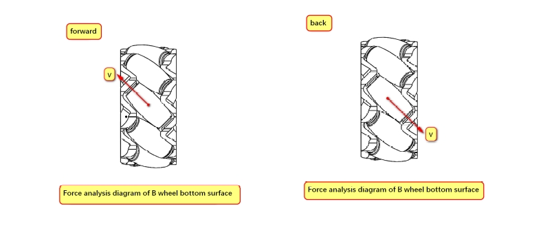
Wheel B
xxxxxxxxxxThe actual direction of movement needs to be determined based on the part of the wheel that contacts the ground
Forward: The actual movement is diagonally to the left front
Backward: The actual movement is diagonally to the right rear
Analysis of the motion state of the car
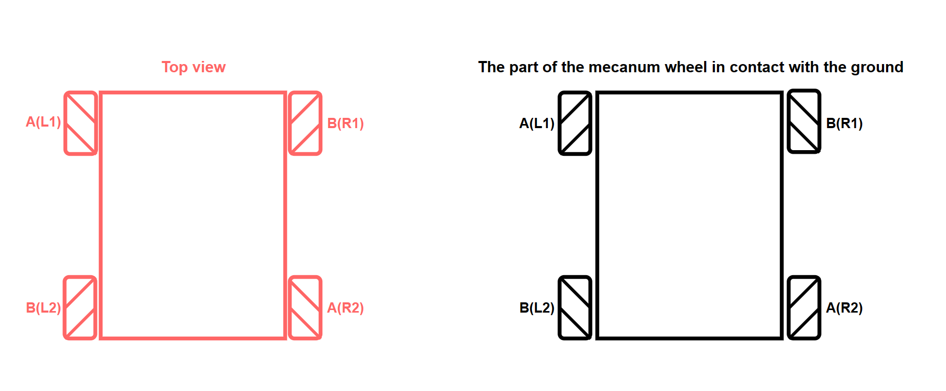
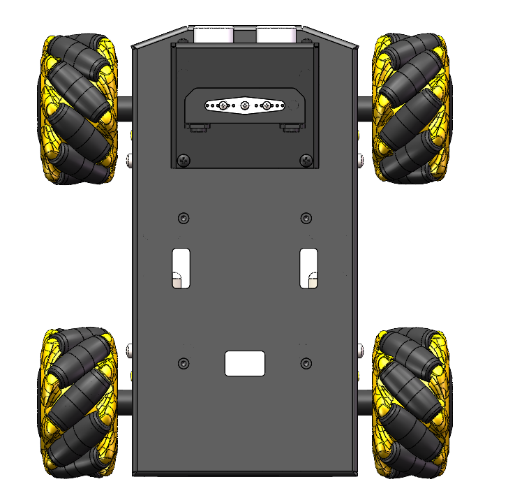
The actual distribution of the Mecanum wheel of our car is ABBA type. The actual installation can refer to the top view in the picture for installation. The stick shape of the Mecanum wheel in the top view is "X-shaped".
xxxxxxxxxxFor motion analysis, it is necessary to refer to the contact part of the Mecanum wheel with the ground for analysis!
Motion decomposition
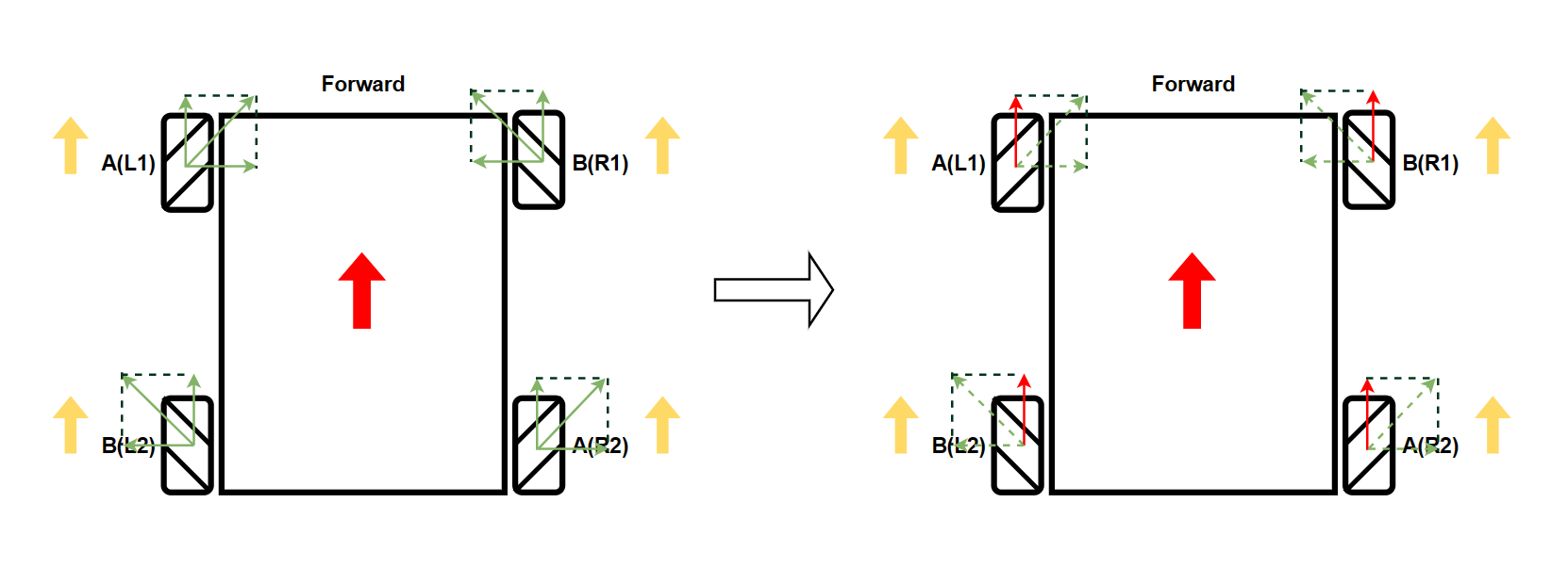
The following figure demonstrates the speed decomposition of the car's forward state.
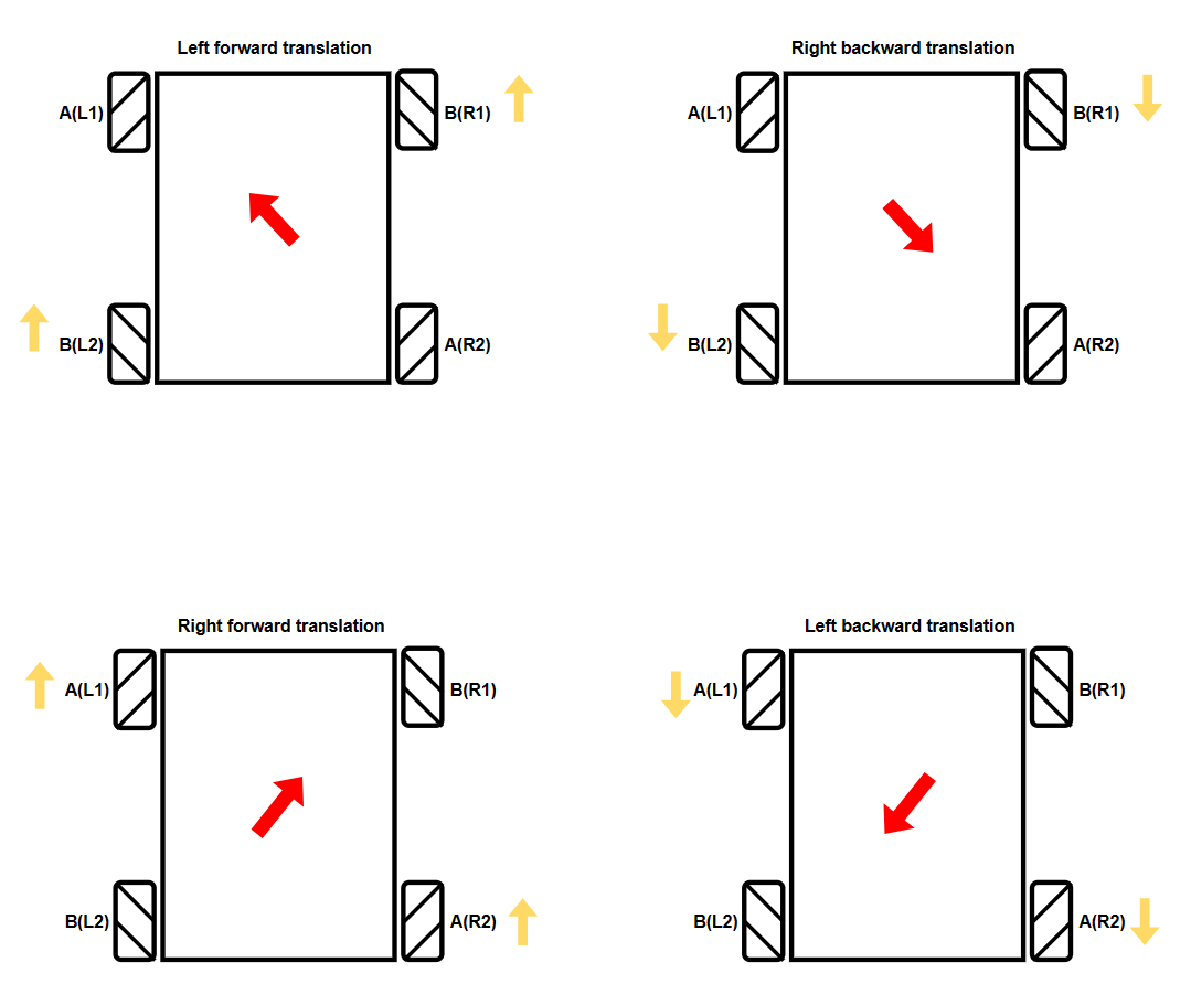
xxxxxxxxxxYellow arrow: motor rotation direction (upward means forward - motor forward rotation, downward means backward - motor reverse rotation)Red arrow: actual movement direction of the carGreen arrow: speed decomposition direction (where the dotted arrow is the speed component after offset, and the red arrow is the actual speed component)
The movement state in the table is analyzed when the speeds of the four motors are consistent and the ground is flat: + represents forward rotation, - represents reverse rotation, and 0 represents no speed.
| Movement Status | L1 | L2 | R1 | R2 |
|---|---|---|---|---|
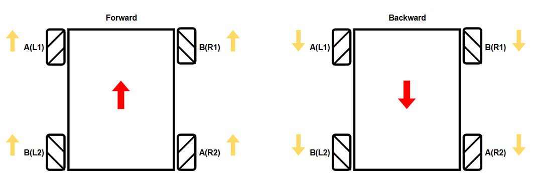
| Forward | + | + | + | + |
| Backward | - | - | - | - |
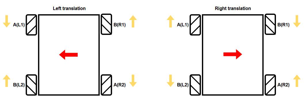
| Left Translation | - | + | + | - |
| Right Translation | + | - | - | + |
| Left Front | 0 | + | + | 0 |
| Left Rear | - | 0 | 0 | - |
| Right Front | + | 0 | 0 | + |
| Right Rear | 0 | - | - | 0 |
| Counterclockwise Rotation (Left Rotation) | - | - | + | + |
| Clockwise Rotation (Right Rotation) | + | + | - | - |
| Stop | 0 | 0 | 0 | 0 |
Forward/Backward
Left/Right Pan
Front/Back Pan
Rotate in Place

Stop

Notes
Due to the influence of factors such as structure, resistance and friction during the actual movement of the car, some movement states are not particularly ideal.
xxxxxxxxxxThe TTL motor equipped with our Robduino car cannot perform PID speed regulation, so some movement states are not particularly ideal