1. Lidar Basics (4ROS Radar)
1.1 Overview
Single-line laser radar refers to a radar whose laser source emits a single-line beam. It is divided into triangulation and TOF laser radar, and is mainly used in the field of robotics. It has fast scanning speed, high resolution and high reliability. Compared with multi-line laser radar, single-line laser radar has a faster response in angular frequency and sensitivity, so it is more accurate in the distance and accuracy of obstacle measurement.
1.2. Principle of single-line laser radar
The working principle of single-line mechanical rotating mechanism radar is shown in the figure below:
1.2.1. Triangulation ranging method
The laser triangulation ranging method mainly uses a laser beam to illuminate the target at a certain incident angle. The laser is reflected and scattered on the target surface. At another angle, the reflected laser is focused by a lens to form an image. The light spot is imaged on the CCD (Charge-coupled Device) position sensor. When the object to be measured moves along the laser direction, the light spot on the position sensor will move, and its displacement size corresponds to the moving distance of the object to be measured. Therefore, the distance between the object to be measured and the baseline can be calculated by algorithm design based on the light spot displacement distance. Since the incident light and the reflected light form a triangle, the geometric trigonometric theorem is used to calculate the spot displacement, so this measurement method is called laser triangulation distance measurement.
According to the angle relationship between the incident light beam and the surface normal of the measured object, the laser triangulation distance measurement method can be divided into two types: oblique type and direct type.
1. Direct type
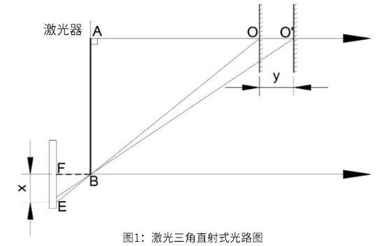
As shown in Figure 1, when the laser beam is incident vertically on the surface of the measured object, that is, the incident light and the surface normal of the measured object are collinear, it is a direct laser triangulation method.
2. Oblique type
In the optical path system, when the angle between the incident laser beam and the surface normal of the measured object is less than 90°, the incident mode is oblique. The optical path diagram shown in Figure 2 is the oblique optical path diagram of the laser triangulation method.
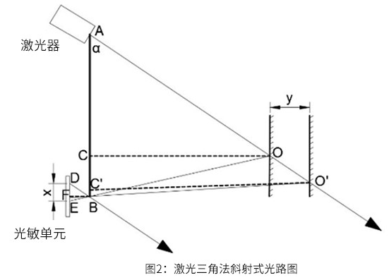
The laser emitted by the laser is incident on the surface of the object to be measured at a certain angle to the normal line of the object surface. The reflected (scattered) light is converged by the lens at B and finally collected by the photosensitive unit.
Both direct and oblique laser triangulation can achieve high-precision, non-contact measurement of the object to be measured, but the resolution of the direct type is not as high as that of the oblique type.
The RPLIDAR series laser radar of Silan Technology also adopts the oblique laser triangulation ranging method. During each ranging process, the RPLIDAR series laser radar will emit a modulated infrared laser signal. The reflection generated by the laser signal after irradiating the target object will be received by the RPLIDAR's visual acquisition system, and then solved in real time by the DSP processor embedded in the RPLIDAR. The distance value between the irradiated target object and the RPLIDAR and the current angle information will be output from the communication interface. Driven by the motor mechanism, the ranging core of RPLIDAR will rotate clockwise, thereby achieving 360-degree all-round scanning and ranging detection of the surrounding environment.
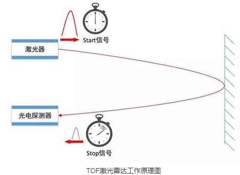
1.2.2, TOF time-of-flight ranging method
TOF laser radar is based on measuring the flight time of light to obtain the distance of the target object. Its working principle is mainly manifested in that a beam of modulated laser signal is emitted by the laser transmitter, and the modulated light is received by the laser detector after being reflected by the object to be measured. The distance of the target can be calculated by measuring the phase difference between the emitted laser and the received laser.
Under the condition of long-distance objects, its measurement accuracy is still accurate and stable. At the same time, due to the characteristics of ultra-short light pulses, TOF radar is also not inferior in anti-light interference ability, and can achieve stable ranging and high-precision mapping even in strong light of 60Klx outdoors.
In general, triangulation ranging laser radar and TOF laser radar have their own difficulties in implementation. In principle, TOF radar has a longer distance. In some occasions where distance is required, TOF radar is mostly used. Triangulation ranging laser radar has a relatively low manufacturing cost and its accuracy can meet most industrial-grade civilian requirements. Therefore, it has also attracted much attention in the industry.
1.3. Use radar
Terminal operation
xsudo supervisorctl stop allsudo supervisorctl start LaserServer #start/stop switch radar serviceWe can print the topic data through the terminal to check whether the radar is started normally. Enter the terminal,
xxxxxxxxxxrostopic echo /scan
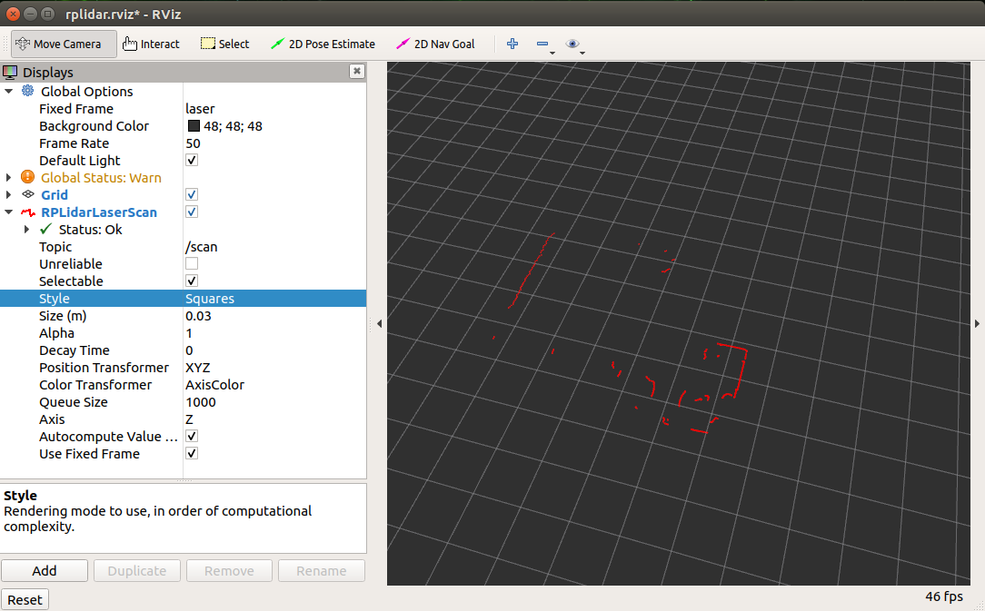
If you want to view the scan results in RVIZ, enter the terminal and configure rviz as shown in the figure below
xxxxxxxxxxrviz
1.4. Launch analysis
Path: /home/yahboom/YBAMR-COBOT-EDU-00001/src/yahboom_navrobo_driver/lidar/ydlidar_ros_driver/launch
TG.launch file
xxxxxxxxxx<launch> <arg name="frame_id" default="laser"/> <node name="ydlidar_lidar_publisher" pkg="ydlidar_ros_driver" type="ydlidar_ros_driver_node" output="screen" respawn="false" > <!-- string property --> <param name="port" type="string" value="/dev/ydlidar"/> <param name="frame_id" type="string" value="$(arg frame_id)"/> <!--param name="ignore_array" type="string" value="-90,90"/--> <param name="ignore_array" type="string" value=""/> <!--remap from="scan" to="scan_raw"/--> <!-- int property --> <param name="baudrate" type="int" value="512000"/> <!-- 0:TYPE_TOF, 1:TYPE_TRIANGLE, 2:TYPE_TOF_NET --> <param name="lidar_type" type="int" value="0"/> <!-- 0:YDLIDAR_TYPE_SERIAL, 1:YDLIDAR_TYPE_TCP --> <param name="device_type" type="int" value="0"/> <param name="sample_rate" type="int" value="20"/> <param name="abnormal_check_count" type="int" value="4"/> <!-- bool property --> <param name="resolution_fixed" type="bool" value="true"/> <param name="auto_reconnect" type="bool" value="true"/> <param name="reversion" type="bool" value="true"/> <param name="inverted" type="bool" value="true"/> <param name="isSingleChannel" type="bool" value="false"/> <param name="intensity" type="bool" value="false"/> <param name="support_motor_dtr" type="bool" value="false"/> <param name="invalid_range_is_inf" type="bool" value="true"/> <param name="point_cloud_preservative" type="bool" value="false"/> <!-- float property --> <param name="angle_min" type="double" value="-90" /> <param name="angle_max" type="double" value="90" /> <param name="range_min" type="double" value="0.01" /> <param name="range_max" type="double" value="50.0" /> <param name="frequency" type="double" value="10.0"/> </node> <!--node pkg="tf" type="static_transform_publisher" name="base_link_to_laser4" args="0.0 0.0 0.2 3.14 0.0 0.0 /base_footprint /laser 40" /--></launch>Main debugging parameters:
- angle_min parameter: left angle of radar
- angle_max parameter: right angle of radar
For other parameters, please refer to the official documentation,
ydlidar_ros_driver/README.md at master · YDLIDAR/ydlidar_ros_driver · GitHub