Read IMU data
Read IMU data1. Experimental purpose2. Hardware connection3. Core code analysis4. Compile, download and flash firmware5. Experimental results
1. Experimental purpose
Use the IMU attitude sensor chip of the microROS control board to learn the function of ESP32 to read IMU device data through the I2C interface.
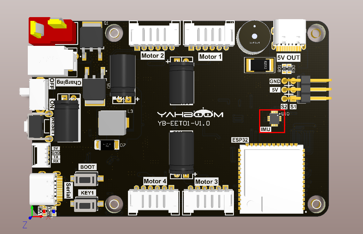
2. Hardware connection
As shown in the figure below, the microROS control board integrates the IMU attitude sensor chip. There is no need to connect additional external devices. You only need to connect the type-C data cable to the computer and the microROS control board for the firmware burning function.
3. Core code analysis
The virtual machine path corresponding to the program source code is as follows:
~/esp/Samples/esp32_samples/read_imu
The IMU sensor chip uses the ICM42670P chip. The ICM42670P chip uses I2C communication to transmit data, so ESP32 needs to be initialized as an I2C host first. I2C_MASTER_GPIO_SDA corresponds to hardware GPIO40, I2C_MASTER_GPIO_SCL corresponds to hardware GPIO39, and the I2C setting communication frequency is 400KHz.
void I2C_Master_Init(void){ESP_LOGI(TAG, "Init I2C master:SCL->GPIO%d, SDA->GPIO%d", I2C_MASTER_GPIO_SCL, I2C_MASTER_GPIO_SDA);i2c_port_t i2c_master_port = I2C_MASTER_NUM;i2c_config_t conf = {.mode = I2C_MODE_MASTER,.sda_io_num = I2C_MASTER_GPIO_SDA,.scl_io_num = I2C_MASTER_GPIO_SCL,.sda_pullup_en = GPIO_PULLUP_ENABLE,.scl_pullup_en = GPIO_PULLUP_ENABLE,.master.clk_speed = I2C_MASTER_FREQ_HZ,};i2c_param_config(i2c_master_port, &conf);ESP_ERROR_CHECK(i2c_driver_install(i2c_master_port, conf.mode, I2C_MASTER_RX_BUF_DISABLE, I2C_MASTER_TX_BUF_DISABLE, 0));}
I2C reads a string of data.
xxxxxxxxxxesp_err_t I2C_Master_Read(uint8_t addr, uint8_t reg, uint16_t len, uint8_t* data){return i2c_master_write_read_device(I2C_MASTER_NUM, addr, ®, 1, data, len, I2C_MASTER_TIMEOUT_MS / portTICK_PERIOD_MS);}
I2C reads a byte.
xxxxxxxxxxuint8_t I2C_Master_Read_Byte(uint8_t addr, uint8_t reg){uint8_t data = 0;i2c_master_write_read_device(I2C_MASTER_NUM, addr, ®, 1, &data, 1, I2C_MASTER_TIMEOUT_MS / portTICK_PERIOD_MS);return data;}
I2C writes a string of data
xxxxxxxxxxesp_err_t I2C_Master_Write(uint8_t addr, uint8_t reg, uint16_t len, uint8_t* data){int ret;uint8_t *buf = (uint8_t *)malloc(len+1);buf[0] = reg;for (int i = 0; i < len; i++){buf[i+1] = data[i];}ret = i2c_master_write_to_device(I2C_MASTER_NUM, addr, buf, len+1, I2C_MASTER_TIMEOUT_MS / portTICK_PERIOD_MS);free(buf);return ret;}
I2C writes a byte.
xxxxxxxxxxesp_err_t I2C_Master_Write_Byte(uint8_t addr, uint8_t reg, uint8_t data){int ret;uint8_t write_buf[] = {reg, data};ret = i2c_master_write_to_device(I2C_MASTER_NUM, addr, write_buf, sizeof(write_buf), I2C_MASTER_TIMEOUT_MS / portTICK_PERIOD_MS);return ret;}
The interrupt pin of ICM42670P corresponds to hardware GPIO41, the mode is set to input mode, and an interrupt callback is added.
xstatic inline void Icm42670p_GPIO_Init(void){gpio_config_t io_conf = {};//interrupt of rising edgeio_conf.intr_type = GPIO_INTR_ANYEDGE;//bit mask of the pinsio_conf.pin_bit_mask = (1ULL<<IMU_GPIO_INT);//set as input modeio_conf.mode = GPIO_MODE_INPUT;//disable pull-up modeio_conf.pull_up_en = 0;io_conf.pull_down_en = 0;gpio_config(&io_conf);//install gpio isr servicegpio_install_isr_service(0);//hook isr handler for specific gpio pingpio_isr_handler_add(IMU_GPIO_INT, gpio_isr_handler, (void*)IMU_GPIO_INT);}
The interrupt callback is triggered when the data of ICM42670P is ready.
xxxxxxxxxxstatic void IRAM_ATTR gpio_isr_handler(void* arg){isr_count++;}
ICM42670P needs to first set the bound I2C read data callback and determine whether the WHO_AM_I flag of the chip is correct.
xxxxxxxxxxstatic int setup_imu_device(const struct inv_imu_serif *icm_serif){int rc = 0;uint8_t who_am_i;/* Init device */rc = inv_imu_init(&icm_driver, icm_serif, imu_callback);if (rc != INV_ERROR_SUCCESS) {ESP_LOGE(TAG, "Failed to initialize IMU!");return rc;}/* Check WHOAMI */rc = inv_imu_get_who_am_i(&icm_driver, &who_am_i);if (rc != INV_ERROR_SUCCESS) {ESP_LOGE(TAG, "Failed to read whoami!");return rc;}if (who_am_i != ICM_WHOAMI) {ESP_LOGE(TAG, "Bad WHOAMI value!");ESP_LOGE(TAG, "Read 0x%02x, expected 0x%02x", who_am_i, ICM_WHOAMI);return INV_ERROR;}ESP_LOGI(TAG, "Read ICM_WHOAMI: 0x%02x", who_am_i);return rc;}
Next, configure the relevant parameters of ICM42670P. The accelerometer range is selected as ±4g, the gyroscope range is ±2000dps, the output frequency is 400hz, and low noise mode is allowed.
xxxxxxxxxxstatic int configure_imu_device(void){int rc = 0;// Low resolution moderc |= inv_imu_set_accel_fsr(&icm_driver, ACCEL_CONFIG0_FS_SEL_4g);rc |= inv_imu_set_gyro_fsr(&icm_driver, GYRO_CONFIG0_FS_SEL_2000dps);// low-noise moderc |= inv_imu_set_accel_frequency(&icm_driver, ACCEL_CONFIG0_ODR_400_HZ);rc |= inv_imu_set_gyro_frequency(&icm_driver, GYRO_CONFIG0_ODR_400_HZ);rc |= inv_imu_enable_accel_low_noise_mode(&icm_driver);rc |= inv_imu_enable_gyro_low_noise_mode(&icm_driver);return rc;}
Create a new task for ICM42670P to update data. After ICM42670P prepares the data, it will read the data in time.
xxxxxxxxxxstatic void Icm42670p_Task(void *arg){ESP_LOGI(TAG, "Start Icm42670p_Task with core:%d", xPortGetCoreID());int rc = 0;Icm42670p_GPIO_Init();setup_mcu(&icm_serif);rc |= setup_imu_device(&icm_serif);rc |= run_self_test();rc |= configure_imu_device();if (rc != INV_ERROR_SUCCESS){icm_start_ok = -1;ESP_LOGI(TAG, "Delete Icm42670p_Task with core:%d", xPortGetCoreID());vTaskDelete(NULL);}get_accel_and_gyr_fsr(&icm_accel_fsr_g, &icm_gyro_fsr_dps);icm_start_ok = 1;ESP_LOGI(TAG, "Icm42670p Init OK");while (1){vTaskDelay(pdMS_TO_TICKS(1));if (isr_count > 0){// ESP_LOGI(TAG, "ISR Count:%d", isr_count);isr_count = 0;rc = Icm42670p_Update_Imu_Data();if (rc < 0){ESP_LOGE(TAG, "Read data error:%d", rc);}}}vTaskDelete(NULL);}
Get the raw data of the ICM42670P accelerometer.
xxxxxxxxxxvoid Icm42670p_Get_Accel_RawData(int16_t accel[3]){accel[0] = icm_accel[0];accel[1] = icm_accel[1];accel[2] = icm_accel[2];}
Get the raw data of the gyroscope of ICM42670P.
xxxxxxxxxxvoid Icm42670p_Get_Gyro_RawData(int16_t gyro[3]){gyro[0] = icm_gyro[0];gyro[1] = icm_gyro[1];gyro[2] = icm_gyro[2];}
Get the scaled data of the accelerometer of ICM42670P
xxxxxxxxxxvoid Icm42670p_Get_Accel_g(float accel_g[3]){accel_g[0] = icm_accel_g[0];accel_g[1] = icm_accel_g[1];accel_g[2] = icm_accel_g[2];}
Obtain the scaled data of the gyroscope of ICM42670P
xxxxxxxxxxvoid Icm42670p_Get_Gyro_dps(float gyro_dps[3]){gyro_dps[0] = icm_gyro_dps[0];gyro_dps[1] = icm_gyro_dps[1];gyro_dps[2] = icm_gyro_dps[2];}
Call the Icm42670p_Init function in app_main to initialize the IMU chip, and then read the IMU scaled accelerometer and gyroscope data every 200 milliseconds in the loop. Since the frequency of IMU data output is 400Hz, in order to read data accurately and effectively, the interval between reading data needs to be greater than 2.5 milliseconds.
xxxxxxxxxxvoid app_main(void){printf("hello yahboom\n");ESP_LOGI(TAG, "Nice to meet you!");Icm42670p_Init();#if ENABLE_DEBUG_IMU_RAWint16_t accel_raw[3] = {0};int16_t gyro_raw[3] = {0};#elsefloat accel_g[3] = {0};float gyro_dps[3] = {0};#endifwhile (1){if (Icm42670p_Start_OK() > 0){#if ENABLE_DEBUG_IMU_RAWIcm42670p_Get_Accel_RawData(accel_raw);Icm42670p_Get_Gyro_RawData(gyro_raw);ESP_LOGI(TAG, "Raw Accel:%d, %d, %d, Gyro:%d, %d, %d",accel_raw[0], accel_raw[1], accel_raw[2], gyro_raw[0], gyro_raw[1], gyro_raw[2]);#elseIcm42670p_Get_Accel_g(accel_g);Icm42670p_Get_Gyro_dps(gyro_dps);ESP_LOGI(TAG, "Accel_g:%f, %f, %f, Gyro_dps:%f, %f, %f",accel_g[0], accel_g[1], accel_g[2], gyro_dps[0], gyro_dps[1], gyro_dps[2]);#endif}vTaskDelay(pdMS_TO_TICKS(200));}}
4. Compile, download and flash firmware
Use a Type-C data cable to connect the virtual machine/computer and the microROS control board. If the system pops up, choose to connect to the virtual machine.
Activate the ESP-IDF development environment. Note that every time you open a new terminal, you need to activate the ESP-IDF development environment before compiling the firmware.
xxxxxxxxxxsource ~/esp/esp-idf/export.sh
Enter the project directory
xxxxxxxxxxcd ~/esp/Samples/esp32_samples/read_imu
Compile, flash, and open the serial port simulator
xxxxxxxxxxidf.py build flash monitor
If you need to exit the serial port simulator, press Ctrl+].
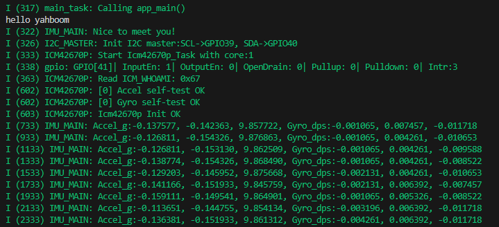
5. Experimental results
The serial port simulator prints the "hello yahboom" greeting. And print the accelerometer and gyroscope scaled data every 200 milliseconds. At this time, shake the microROS control board and you can see that the data will change.