Serial communication
Serial communication1. Experimental purpose2. Hardware connection3. Core code analysis4. Compile and download the burning firmware5. Experimental results
1. Experimental purpose
Use the serial port on the microROS control board to learn how the serial port receives and sends data.
2. Hardware connection
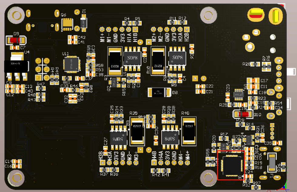
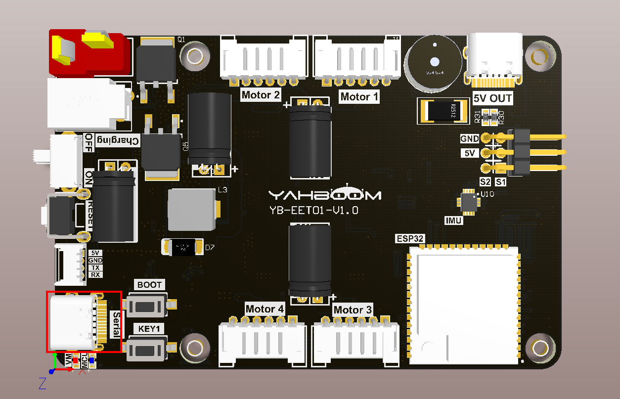
As shown in the figure below, the CP2102 serial port is an onboard component. To convert the serial port signal into a USB signal, a type-C data cable needs to be connected to the computer and the microROS control board for firmware burning and serial communication functions.
3. Core code analysis
The virtual machine path corresponding to the program source code is as follows
~/esp/Samples/esp32_samples/uart
Since the usage methods of serial port 0 and serial port 1 are basically the same, the difference lies in the different pins. UART1_GPIO_TXD of serial port 1 corresponds to hardware GPIO17, and UART1_GPIO_RXD corresponds to hardware GPIO18. Since serial port 1 is used for lidar communication, the baud rate is set to 230400, while serial port 0 is used for communication with a baud rate of 115200.
Here we take serial port 0 as an example.
Initialize the GPIO of serial port 0, where UART0_GPIO_TXD corresponds to hardware GPIO43, and UART0_GPIO_RXD corresponds to hardware GPIO44. Set the baud rate of serial port 0 to 115200, 8-bit data, 1-bit stop, and no parity. At the same time, initialize the receiving buffer ringbuffer of serial port 0 and open serial port 0 to receive background tasks.
xvoid Uart0_Init(void){const uart_config_t uart_config = {.baud_rate = 115200,.data_bits = UART_DATA_8_BITS,.parity = UART_PARITY_DISABLE,.stop_bits = UART_STOP_BITS_1,.flow_ctrl = UART_HW_FLOWCTRL_DISABLE,.source_clk = UART_SCLK_DEFAULT,};uart_driver_install(UART_NUM_0, RX0_BUF_SIZE * 2, 0, 0, NULL, 0);uart_param_config(UART_NUM_0, &uart_config);uart_set_pin(UART_NUM_0, UART0_GPIO_TXD, UART0_GPIO_RXD, UART_PIN_NO_CHANGE, UART_PIN_NO_CHANGE);RingBuffer_Init(&uart0_ringbuf, RX0_BUF_SIZE);xTaskCreate(Uart0_Rx_Task, "Uart0_Rx_Task", 5*1024, NULL, configMAX_PRIORITIES, NULL);}
The serial port 0 background receiving task is mainly to cache the received serial port data and store it in the ringbuffer, which can achieve the data first-in-first-out function.
xstatic void Uart0_Rx_Task(void *arg){ESP_LOGI(TAG, "Start Uart0_Rx_Task with core:%d", xPortGetCoreID());uint16_t temp_len = 255;uint8_t* temp_data = (uint8_t*) malloc(temp_len);while (1){// 从串口0读取数据,并将读取的数据缓存到ringbuffer里。// Data is read from serial port 0 and cached into ringbuffer.const int rxBytes = uart_read_bytes(UART_NUM_0, temp_data, temp_len, 1 / portTICK_PERIOD_MS);if (rxBytes > 0){for (int i = 0; i < rxBytes; i++){RingBuffer_Push(&uart0_ringbuf, temp_data[i]);}}vTaskDelay(pdMS_TO_TICKS(1));}free(temp_data);vTaskDelete(NULL);}
Serial port 0 sends a string of data.
xxxxxxxxxxint Uart0_Send_Data(uint8_t* data, uint16_t len){const int txBytes = uart_write_bytes(UART_NUM_0, data, len);return txBytes;}
Serial port 0 sends one byte.
xxxxxxxxxxint Uart0_Send_Byte(uint8_t data){uint8_t data1 = data;const int txBytes = uart_write_bytes(UART_NUM_0, &data1, 1);return txBytes;}
Determine whether there is data in the cache of serial port 0 and return the number of data cached in serial port 0.
xxxxxxxxxxuint16_t Uart0_Available(void){return RingBuffer_Get_Used_Count(&uart0_ringbuf);}
Read one byte from serial port 0 cache data
xxxxxxxxxxuint8_t Uart0_Read(void){ return RingBuffer_Pop(&uart0_ringbuf);}Clear the cached data of serial port 0.
xxxxxxxxxxvoid Uart0_Clean_Buffer(void){RingBuffer_Clean_Queue(&uart0_ringbuf);}
Call the Uart0_Init and Uart1_Init functions in app_main to initialize serial port 0 and serial port 1, and read whether serial port 0 and serial port 1 have cached data in the loop. If there is cached data, the data will be sent out, thereby realizing the "self-receiver and self-send" function. .
xxxxxxxxxxvoid app_main(void){printf("hello yahboom\n");ESP_LOGI(TAG, "Nice to meet you!");vTaskDelay(pdMS_TO_TICKS(100));Uart0_Init();Uart1_Init();uint16_t uart0_rx_len = 0;uint16_t uart1_rx_len = 0;int i = 0;while (1){uart0_rx_len = Uart0_Available();if (uart0_rx_len){for (i = 0; i < uart0_rx_len; i++){Uart0_Send_Byte(Uart0_Read());}}uart1_rx_len = Uart1_Available();if (uart1_rx_len){for (i = 0; i < uart1_rx_len; i++){Uart1_Send_Byte(Uart1_Read());}}vTaskDelay(pdMS_TO_TICKS(1));}}
4. Compile and download the burning firmware
Use a Type-C data cable to connect the virtual machine/computer and the microROS control board. If the system pops up, choose to connect to the virtual machine.
Activate the ESP-IDF development environment. Note that every time you open a new terminal, you need to activate the ESP-IDF development environment before compiling the firmware.
xxxxxxxxxxsource ~/esp/esp-idf/export.sh
Enter the project directory
xxxxxxxxxxcd ~/esp/Samples/esp32_samples/uart
Compile, flash, and open the serial port simulator
xxxxxxxxxxidf.py build flash monitor
If you need to exit the serial port simulator, press Ctrl+].
5. Experimental results
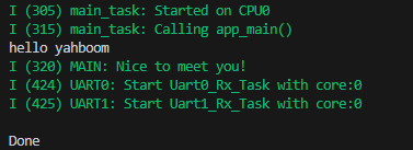
The serial port simulator prints the "hello yahboom" greeting. At this time, press Ctrl+] to exit the serial port simulator.
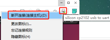
Re-plug the Type-C serial port cable of the microROS control board, and then choose to connect to the host.
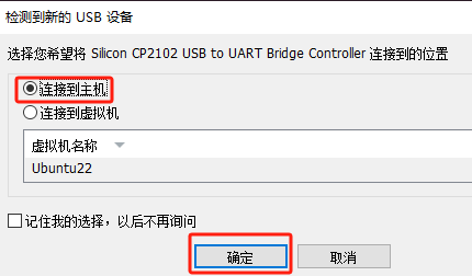
Or find the CP2102 device icon in the upper right corner of the virtual machine software, right-click and select Disconnect (connect to host).
At this time, the microROS control board is connected to the host and the serial port debugging assistant of the host is opened.
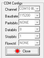
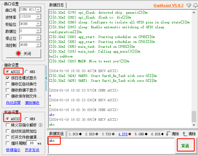
Search for the device number of CP2102 and open the serial port. The baud rate is 115200, 8-bit data, 1-bit stop, no parity, and no flow control. Select ASCII character mode in receive settings and send settings. Then enter any characters in the send box and press send. The serial port will send the received characters back. Thus realizing the function of spontaneous and self-receiving of the serial port.
Chinese serial port assistant software example renderings:
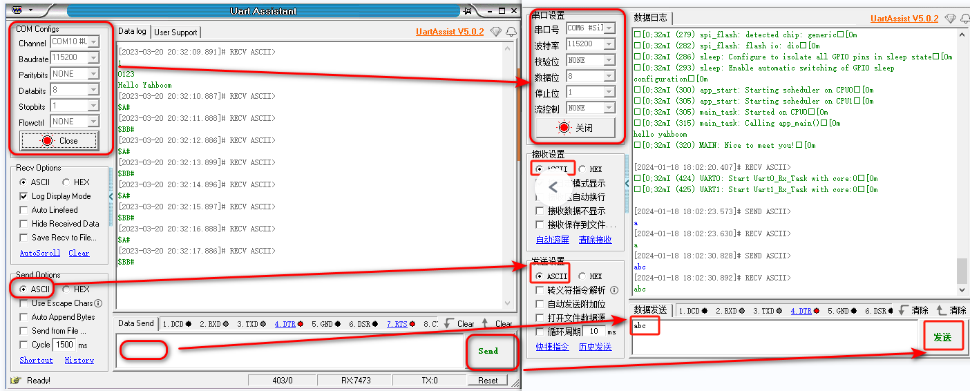
The English interface can be set using the serial port Chinese picture example:
After the experiment, please click to close the serial port.