9.MIPI CSI DSI connector
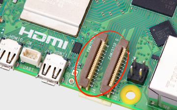
The CSI and DSI ports found on previous models of Raspberry Pi have been combined into two dual-purpose CSI/DSI (MIPI) ports. To fit onto the board these now use a denser connector pinout, previously only found on Raspberry Pi Zero and the CM4IO board. You can connect two displays, two cameras, or one camera and one display to these ports.
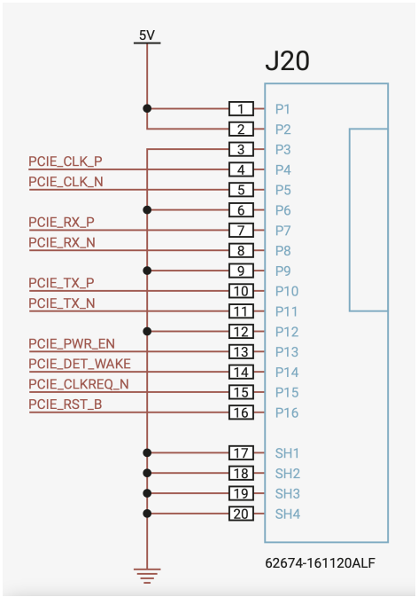
Schematic diagram of interface line sequence
Attaching cameras
There is no configuration necessary for Raspberry Pi devices like cameras. If you plug a camera into either MIPI connector you will get an appropriate CSI connection, and your camera will be made available to the OS.
Attaching a display
If you are using our 7-inch Touch Display with Raspberry Pi 5, it will not automatically be configured. You will need to add one of the following two lines to your /boot/firmware/config.txt file. Attaching the display to the CAM/DISP 1 connector you should add:
dtoverlay=vc4-kms-dsi-7inch
Alternatively, attaching it to the CAM/DISP 0 connector you can add the following line:
xxxxxxxxxxdtoverlay=vc4-kms-dsi-7inch,dsi0
Available display cables
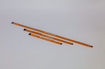
There are three Flat Flexible Cables (FFC) available to connect DSI displays to the Raspberry Pi 5:
- 200 mm display cable standard to mini
- 300 mm display cable standard to mini
- 500 mm display cable standard to mini
Using non-Raspberry Pi devices
If you are using a non-Raspberry Pi MIPI device — either a camera, or a display — it will not be automatically configured for your Raspberry Pi 5. Instead you will need to add a dtoverlay setting into the /boot/firmware/config.txt file to correctly configure the right port for the right camera or display.
These dtoverlay settings should be provided by the manufacturer of your device. For example, adding dtoverlay=ov9281 would configure an Omnivision OV9281-based camera on CSI/DSI1, while adding dtoverlay=ov9281,cam0 would add the same camera to CSI/DSI0.