Advanced timers
Advanced timers1、software-hardware2、Brief principle2.1、Hardware interface2.2、Physical connection diagram2.3、Principle of control3、Engineering configuration3.1、Notes3.2、Pin configuration4、Main function4.1、User functions4.2、HAL library functions5、Experimental phenomenon
This tutorial shows how to generate a PWM signal with a known frequency and duty cycle from the Universal Timer (TIM3) , measure the frequency and duty cycle of this known PWM signal using the PWM input mode of the ** Advanced Timer (TIM1) , and print the relevant data via the serial port (USART1) **.
1、software-hardware
STM32F103CubeIDE
STM32 robot expansion board
TIM: Chip internal peripherals
Mother to mother dupont wire: 1
Type-C cable or ST-Link
Download or simulate the program of the development board
2、Brief principle
2.1、Hardware interface
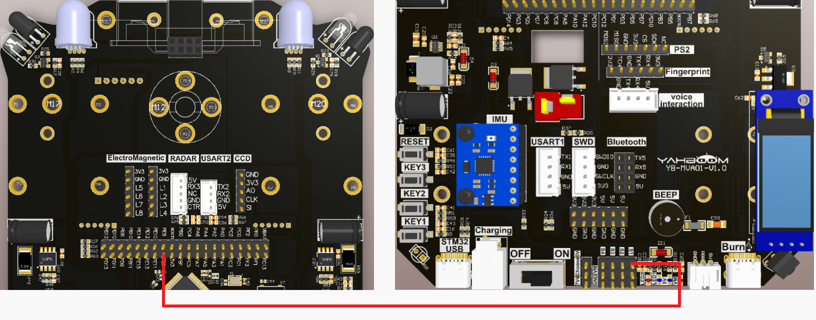
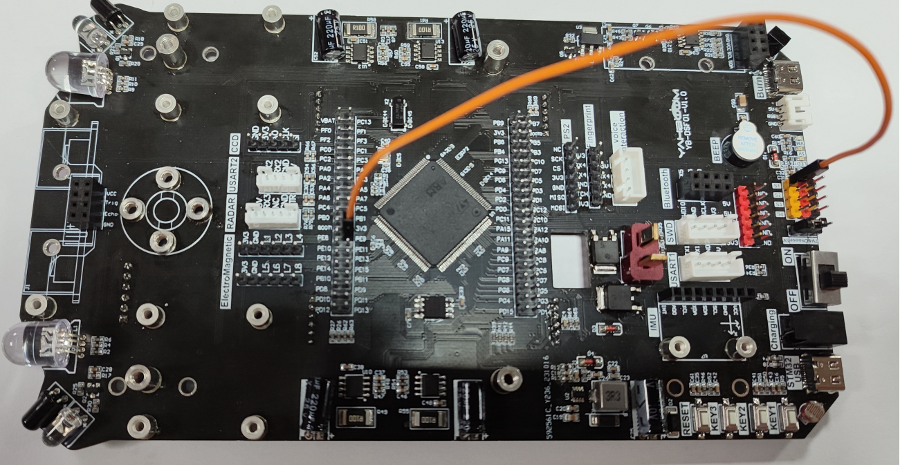
2.2、Physical connection diagram
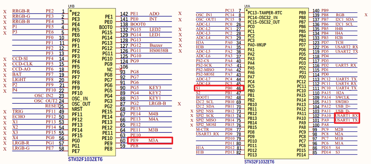
This tutorial requires connecting the S1 signal wire (yellow terminal) and PE9 pin of the servo
2.3、Principle of control
TIM1:The timer PWM input mode is configured to measure the frequency and duty cycle of the known PWM signal
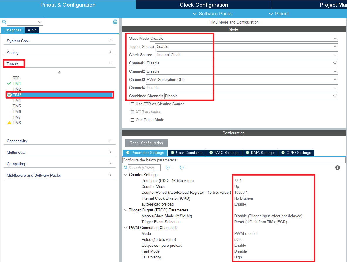
TIM3:The timer PWM output mode is configured to generate PWM signals with known frequency and duty cycle
- Advanced timers
| Timer types | Advanced timers |
|---|---|
| The timer name | TIM1、TIM8 |
| Number of counter bits | 16 |
| Counting mode | Increase/decrease/center alignment |
| Predivision coefficient | 1-65536 |
| Generating DMA requests | Yes |
| Capture/compare channels | 4 |
| Complementary output | Yes |
| Clock frequency | 72MHz(Max) |
| Mount bus | APB2 |
Time base cell
| register | Function |
|---|---|
| The counter register(TIMx_CNT) | The current value of the counter |
| Predivider register(TIMx_PSC) | Set frequency division coefficient (1-65536) |
| Automatically reload registers(TIMx_ARR) | The counter counts the boundary and the overloaded value |
| Repeat count register(TIMx_RCR) | Set the repeat counter value |
Timing formula
| parameters | meaning |
|---|---|
| T(s) | Timing time in seconds |
| ARR | Automatically reload the value |
| PSC | Predivision coefficient |
| TIM_CLK | The timer ticks in Hz |
PWM period:T = 10ms → f = 100Hz
- PWM input mode
When PWM input mode is used, one input channel (TIx) will occupy two capture channels (ICx), and the two ICx signals are valid for edges, but with opposite polarity.
Measure pulse width and frequency
PWM is measured in PWM input mode, PWM signal input can only be input from channel 1 (CH1) or channel 2 (CH2).
Consider input channel TI1 working in PWM input mode:
The PWM signal enters through the input channel TI1, and the signal will be divided into two channels, one is TI1FP1, and the other is TI1FP2.
Choose the effective polarity of TI1FP1: effective → period on the rising edge
The effective polarity of TI1FP2 is chosen: effective → duty cycle on the falling edge
When using PWM input mode, the slave mode controller must be configured to reset mode, that is, when we start the trigger signal to start the capture, we also reset the counter CNT to zero.
PWM input mode timing
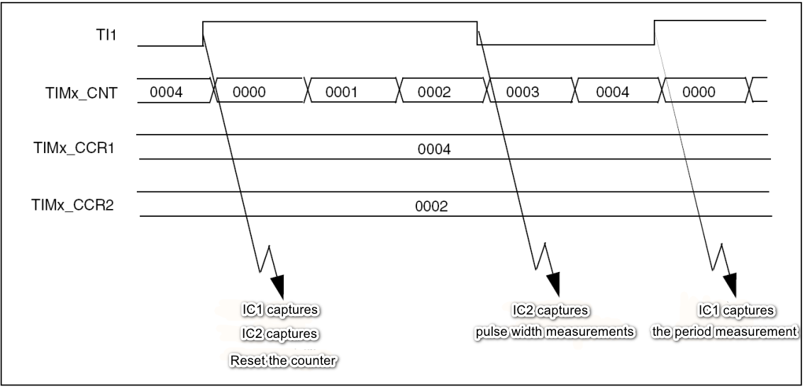
The PWM signal is entered by the input channel TI1, and TI1FP1 is configured as the trigger signal, and the rising edge is captured. When the rising edge is captured by IC1 and IC2, the counter CNT is reset. When the falling edge is reached, IC2 is captured and the value of counter CNT is latched into the capture register CCR2. When the next rising edge is reached, IC1 is captured and the value of counter CNT is latched into the capture register CCR1. Among them, CCR2 measures pulse width and CCR1 measures period.
3、Engineering configuration
3.1、Notes
Omitted project configuration: New project, chip selection, project configuration, SYS for pin configuration, RCC configuration, clock configuration, and project configuration content
The project configuration part, which is not omitted, is the key point to configure in this tutorial.
xxxxxxxxxxPlease refer to [2. Development environment construction and use: STM32CubeIDE installation and use] to understand how to configure the omitted parts of the project.
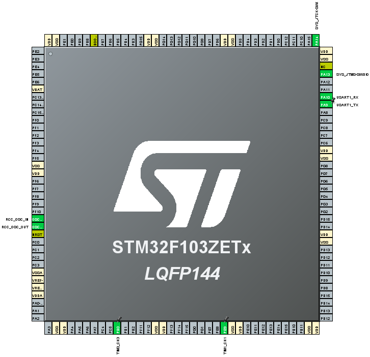
3.2、Pin configuration
- Configure the specified pin function
You can directly select the corresponding pin number in the pin view, and the corresponding option will appear when the mouse is left clicked
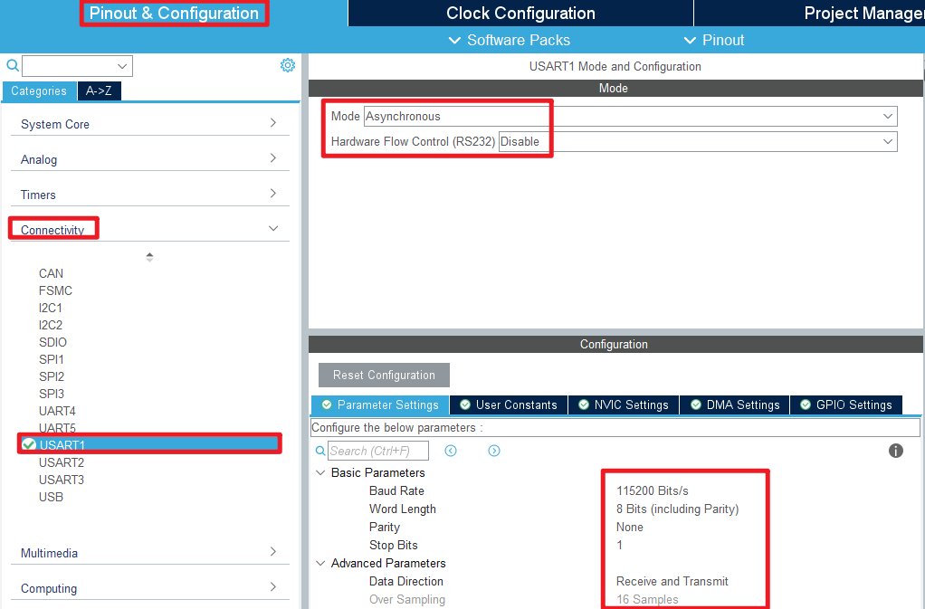
- USART
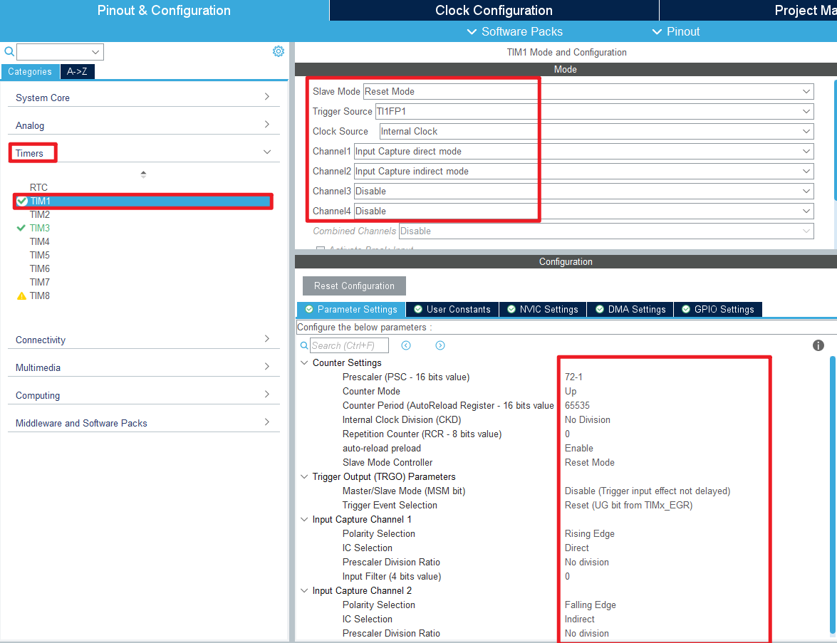
- TIM1
- TIM3
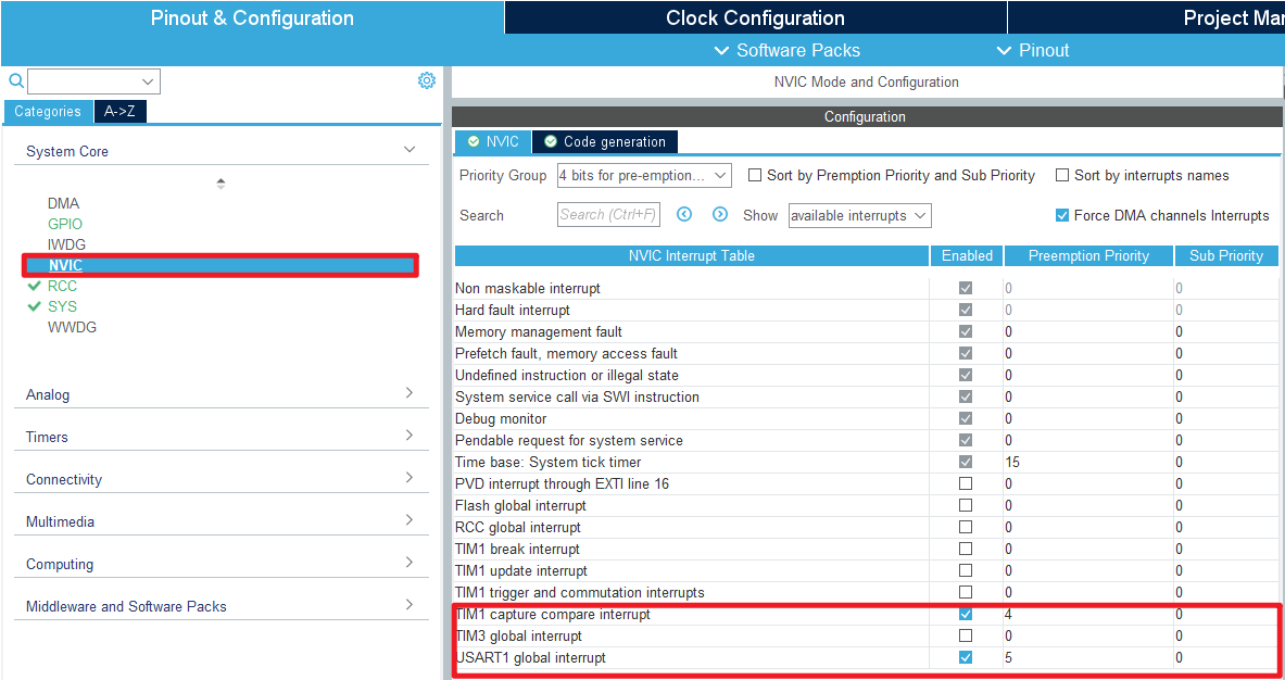
- NVIC
The NVIC option allows you to change the priority
- Advanced Settings
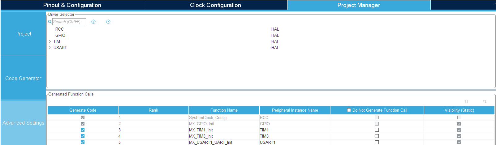
- Generating code

4、Main function
For detailed code, you can open the project file provided by us and go to the Bsp folder to view the source code.
4.1、User functions
HAL_TIM_IC_CaptureCallback
| Function prototypes | void HAL_TIM_IC_CaptureCallback(TIM_HandleTypeDef *htim) |
|---|---|
| Functional Description | The input capture interrupt event used to process the timer |
| Input parameters | htim:Timer handle address |
| Return value | None |
| notes | Inside the function, you can write code to handle input capture events, such as reading the capture register value, calculating the pulse width, and so on |
In the HAL_TIM_IC_CaptureCallback function, we read the counts of IC1 and IC2, which are multiplied by a single count plus 1 to give the period and pulse width.
4.2、HAL library functions
The HAL library functions that were covered in the previous tutorial will not be covered
xxxxxxxxxxIf you want to find the HAL library and LL library function analysis involved in the entire tutorial, you can view the documents in the folder [8. STM32 Manual: STM32F1_HAL Library and LL Library_User Manual]
function:HAL_TIM_PWM_Init
| Function prototypes | HAL_StatusTypeDef HAL_TIM_PWM_Init(TIM_HandleTypeDef *htim) |
|---|---|
| Functional Description | Initialize the timer's PWM output mode |
| Input parameters | htim:Timer handle address |
| Return value | HAL status value:HAL_OK、HAL_ERROR、HAL_BUSY、HAL_TIMEOUT |
function:HAL_TIM_MspPostInit
| Function prototypes | void HAL_TIM_MspPostInit(TIM_HandleTypeDef* timHandle) |
|---|---|
| Functional Description | Peripheral clock, GPIO, and NVIC to initialize the timer |
| Input parameters | htim:Timer handle address |
| Return value | None |
| notes | The function performs additional initialization on top of HAL_TIM_Base_MspInit |
function:HAL_TIM_PWM_Start
| Function prototypes | HAL_StatusTypeDef HAL_TIM_PWM_Start(TIM_HandleTypeDef *htim, uint32_t Channel) |
|---|---|
| Functional Description | Start PWM output |
| Input parameters1 | htim:Timer handle address |
| Input parameters2 | Channel:Timer channel number |
| Return value | HAL status value:HAL_OK、HAL_ERROR、HAL_BUSY、HAL_TIMEOUT |
function:HAL_TIM_PWM_ConfigChannel
| Function prototypes | HAL_StatusTypeDef HAL_TIM_PWM_ConfigChannel (TIM_HandleTypeDef *htim, const TIM_OC_InitTypeDef *sConfig, uint32_t Channel) |
|---|---|
| Functional Description | Set the PWM channel for the timer |
| Input parameters1 | htim:Timer handle address |
| Input parameters2 | sConfig:The timer outputs the comparison parameters |
| Input parameters3 | Channel:Timer channel number |
| Return value | HAL status value:HAL_OK、HAL_ERROR、HAL_BUSY、HAL_TIMEOUT |
function:HAL_TIM_IC_Init
| Function prototypes | HAL_StatusTypeDef HAL_TIM_IC_Init(TIM_HandleTypeDef *htim) |
|---|---|
| Functional Description | Initialize the input capture function of the timer |
| Input parameters | htim:Timer handle address |
| Return value | HAL status value:HAL_OK、HAL_ERROR、HAL_BUSY、HAL_TIMEOUT |
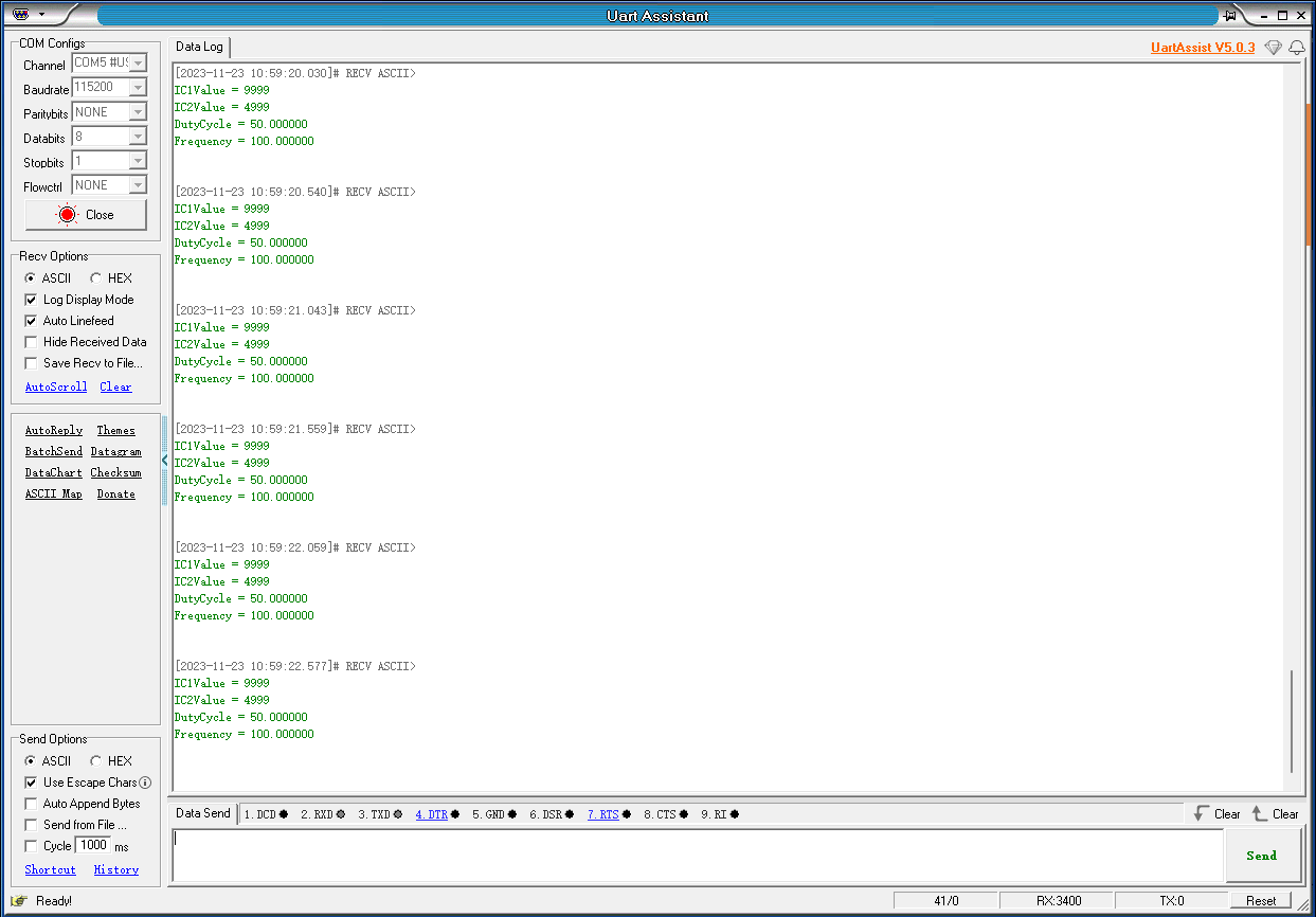
5、Experimental phenomenon
After downloading the program successfully, press the RESET button of the development board to open the serial debugging assistant to observe the phenomenon
xxxxxxxxxxFor program download, please refer to [2. Development environment construction and use: program download and simulation]
Phenomenon:You can see that the data displayed by the serial port is the same as the PWM signal data generated by the universal timer (TIM3).