9. Timer interrupt to control PWM servo
9. Timer interrupt to control PWM servo 9.1. Purpose of the experiment 9.2, configuration pin information 9.3. Analysis of the experimental flow chart 9.4. core code explanation 9.5. Hardware connection 9.6. Experimental effect
9.1. Purpose of the experiment
Use the basic timer interrupt function of STM32 to simulate the output PWM signal and control the PWM servo.
9.2, configuration pin information
- Import the ioc file from the Beep project and name it PwmServo.
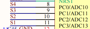
According to the schematic diagram, the servos S1 S2 S3 S4 are connected to the PC3 PC2 PC1 PC0 pins of the STM32 respectively.
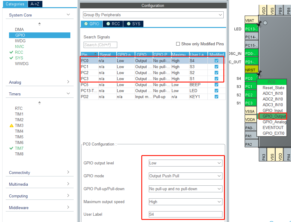
Set the PC0 PC1 PC2 PC3 pins as output mode, the specific parameters are shown in the following figure:
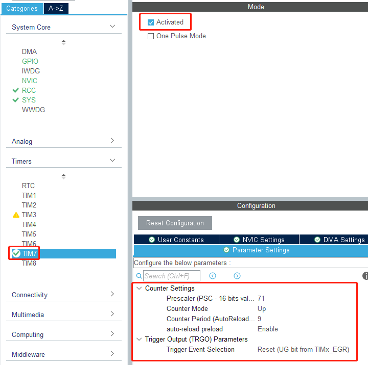
- Next, we need to configure timer 7. The specific configuration parameters are shown in the figure below.
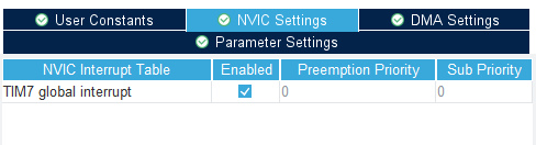
Turn on the timer global interrupt setting.
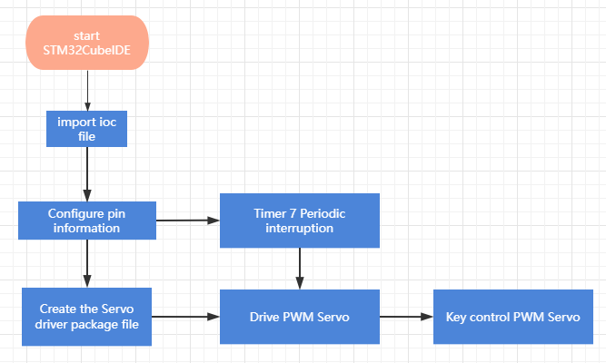
9.3. Analysis of the experimental flow chart
9.4. core code explanation
- Create new bsp_pwmServo.h and bsp_pwmServo.c, and add the following content in pwmServo.h:
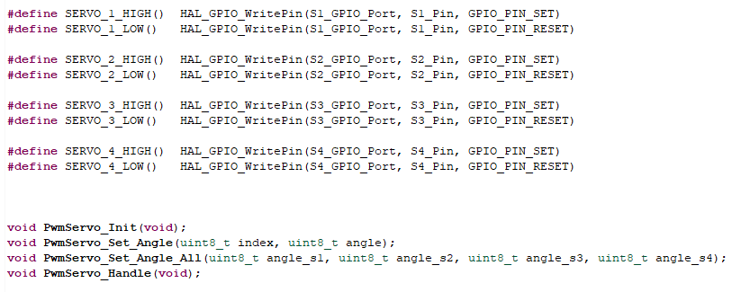
Among them, SERVO_X_HIGH() means output high level, SERVO_X_LOW() means output low level.
- Create the following content in the bsp_pwmServo.c file:
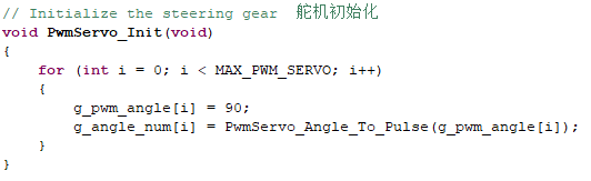
The PwmServo_Init() function initializes the PWM position to 90 degrees.
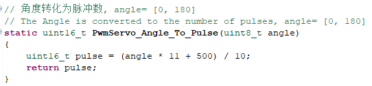
The PwmServo_Angle_To_Pulse() function converts the angle into a PWM duty cycle value.
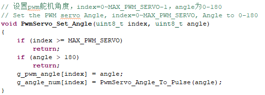
- The PwmServo_Set_Angle() function sets the pwm servo angle, index=0~3, and angle is 0-180.
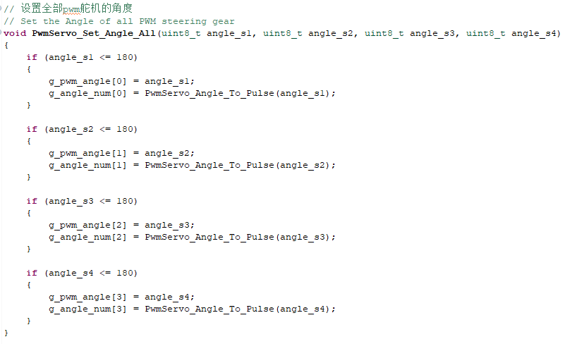
- The PwmServo_Set_Angle_All() function sets the angle of all pwm servos, angle_s1 corresponds to the angle of S1, the range is 1-180, and the other three parameters correspond to the angle values of S2, S3 and S4 respectively.
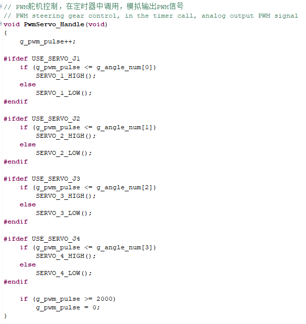
- The PwmServo_Handle() function needs to be called in the interrupt of the timer to simulate the output PWM signal and control the servo according to the angle value of the servo set above.
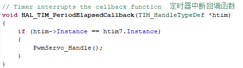
- Create a new HAL_TIM_PeriodElapsedCallback() function. The name of this function cannot be changed, otherwise the function will be found. The PwmServo_Handle() function is called by the timer 7 interrupt to generate the PWM signal.
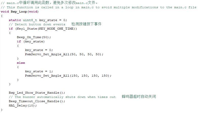
- Add the following content to the Bsp_Loop() function and press the button to control the PWM servo.
9.5. Hardware connection
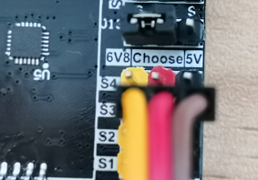
Since the PWM servos have different voltage drive values, the expansion board has added a voltage switching function. According to the jumper cap on the expansion board, the PWM output voltage can be modified to 5V or 6.8V. To use the PWM servo, the corresponding voltage must be selected with a jumper cap to avoid burning the servo. The PWM servos cannot be controlled without the jumper caps inserted. The pins of the PWM servo are: yellow->signal, red->power positive, black->power negative.
Since the power of the PWM servo is relatively large, the expansion board should not be powered by USB 5V directly, but must be powered by DC 12V.
9.6. Experimental effect
After the program is programmed, the LED light flashes every 200 milliseconds. Press the button multiple times, the PWM servo will go back and forth between 50 degrees and 150 degrees.