13. Timer Capture Encoder Data
13. Timer Capture Encoder Data13.1. Purpose of the experiment13.2 Configuring pin information13.3. Experimental flowchart analysis13.4. Core code explanation13.5 Hardware Connection13.6. Experimental Effect
13.1. Purpose of the experiment
Capture encoder data using the STM32's timer encoder mode function.
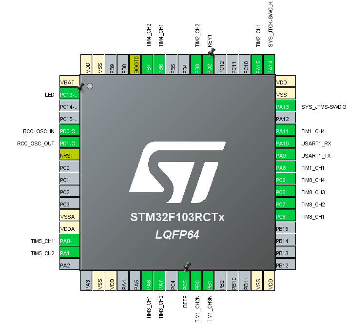
13.2 Configuring pin information
- Import the ioc file from Motor's project and name it Encoder, then serial port 1's related driver.
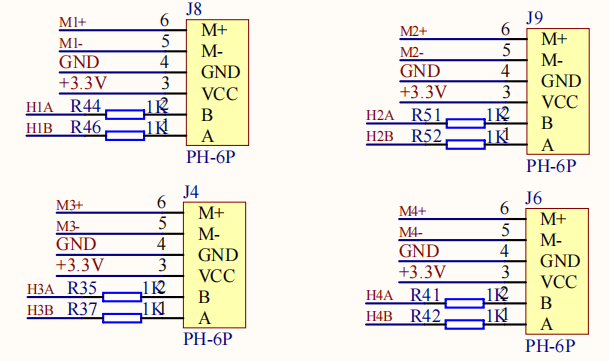
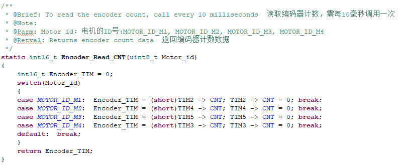
According to the schematic diagram, it can be seen that the two encoders of the four motors are connected to channel 1 and channel 2 of timer 2 3 4 5 respectively. Where motor M1 corresponds to timer TIM2, M2 corresponds to TIM4, M3 corresponds to corresponds to TIM5 and M4 corresponds to TIM3.
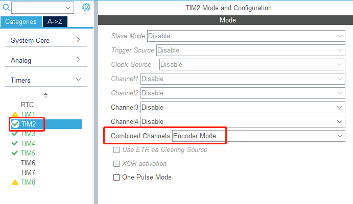
- Take Timer TIM2 for example, TIM3 TIM4 TIM5 is set in the same way. Select Combined Channels mode as Encoder Mode.
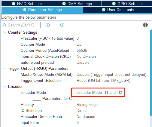
- In the settings, change Encoder Mode to Encoder Mode TI1 and TI2, set it to Quadruple Frequency, and other parameters are shown in the figure below.
The final chip configuration pins are shown below:
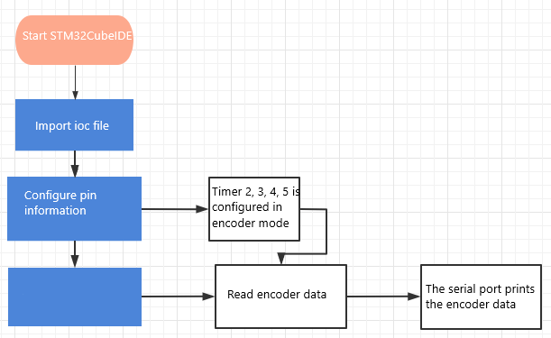
13.3. Experimental flowchart analysis
13.4. Core code explanation
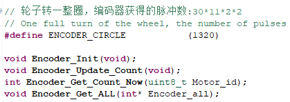
- Create a new bsp_encoder.h and bsp_encoder.c and add the following to bsp_encoder.h:
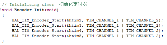
- Create the following new contents in the bsp_encoder.c file:
Encoder timer initialization.
- Read the data from the encoder.
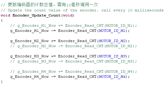
- Updates the total value of the encoder count. Needs to be called every 10 milliseconds.
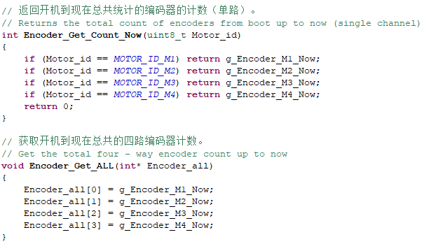
- Return the total number of encoder counts from power on to now, Encoder_Get_Count_Now returns one way, Encoder_Get_ALL returns four ways.
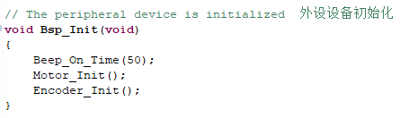
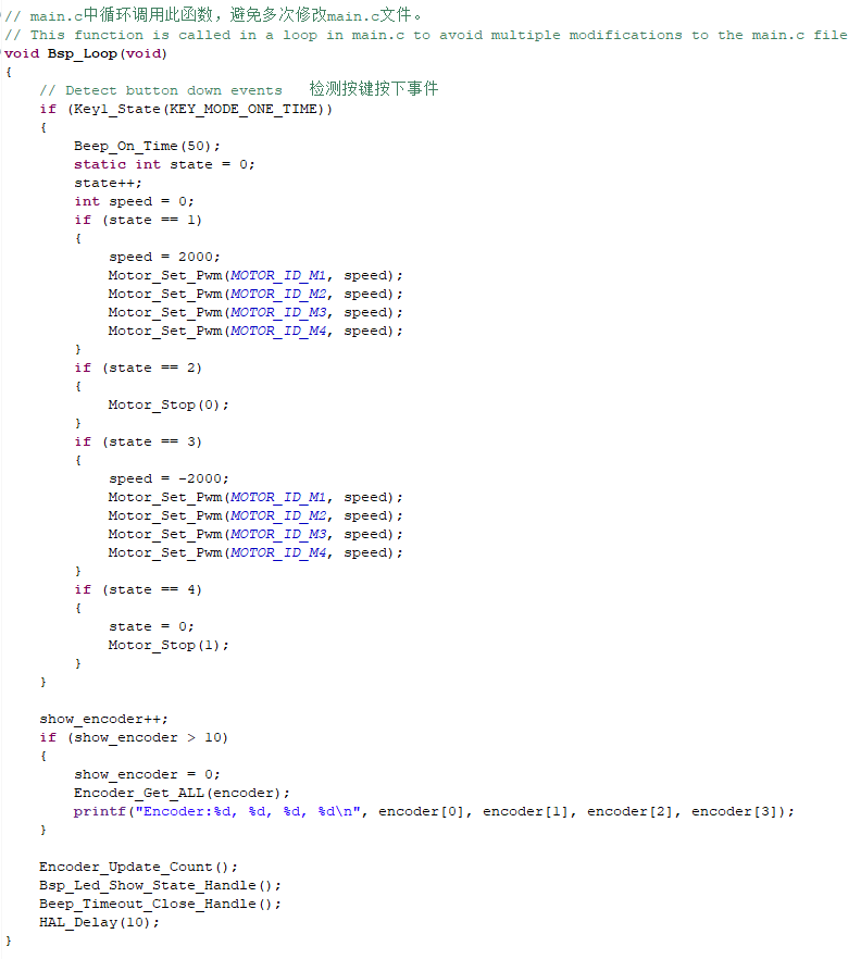
- Add the encoder initialization to the Bsp_Init() function.
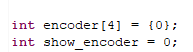
- The new encoder array is used to save the encoder data and show_encoder is used to print the encoder count.
- On the basis of the original control motor, add the function of printing encoder data every 100 milliseconds.
13.5 Hardware Connection
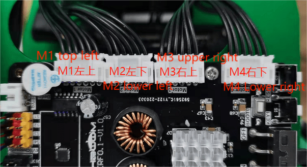
The motor connecting wires need to be connected to the corresponding motors as shown in the following figure, otherwise it may cause the problem that the program does not match the phenomenon. Motor 1 corresponds to the motor in the upper left corner of the body, Motor 2 corresponds to the motor in the lower left corner, Motor 3 corresponds to the motor in the upper right corner, and Motor 4 corresponds to the motor in the lower right corner.
Due to the relatively high power of the motor, the expansion board should not be powered directly by USB 5V, but must be powered by DC 12V.
Then connect the micro-USB cable to the expansion board and computer.
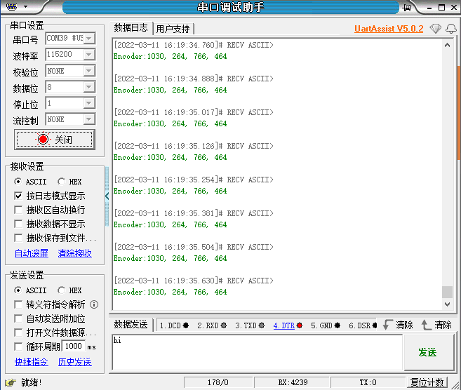
13.6. Experimental Effect
As the motor will start to turn, please set up the cart before the experiment, the motor wheels are suspended, to avoid running across the road.
After burning the program, the LED flashes every 200 milliseconds. Open the serial assistant, you can see the encoder data. Press the first forward, the second free stop, the third backward, the fourth brake stop.