2. STM32 development environment
2. STM32 development environment 2.1. STM32CubeIDE profile2.2. Downloading the installer2.3. Start installation2.4. New construction project2.5. Pin configuration2.6. Write code2.7. Compiling programs2.8. SWD burn firmware2.9. ISP burn program2.10. Procedural phenomenon
2.1. STM32CubeIDE profile
STM32CubeIDE is an all-in-one multi-operating system development tool, an advanced C/C++ development platform with peripherals configuration, code generation, code compilation and debugging capabilities for STM32 microcontrollers and microprocessors. It is based on the Eclipse®/CDT™ framework and GCC toolchain for development, as well as GDB for debugging, can select an STM32 microprocessor and then create a project and generate initialization code, support graphical configuration of STM32 clock and pin content, support Windows, Linux, Mac mainstream platforms, It is very powerful and practical.
2.2. Downloading the installer
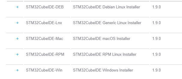
Open the following link in your computer browser:
https://www.st.com/zh/development-tools/stm32cubeide.html
According to the computer system download, here to install the Win10 system 1.9.0 version as an example, choose the latest version to download.
If you have an account on my.st.com, you can log in and download the software directly. If you don't want to log in right now, just provide your name and email address in the form below to download the software.
Decompress the downloaded file in a path that does not contain Chinese characters.
2.3. Start installation
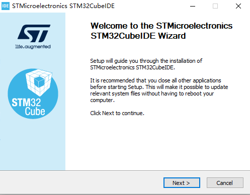
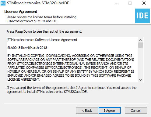
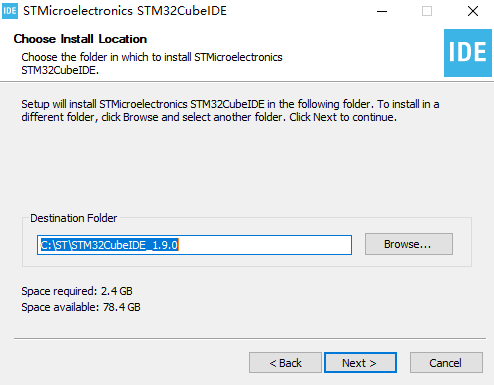
Double-click to open the installer.Then follow along with the tutorial.
The installation path can be changed based on the actual situation. Do not contain Chinese characters.
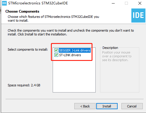
Select the driver, then click Install to install.
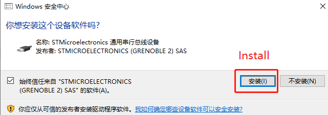
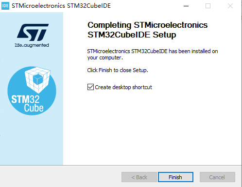
Then wait for the installation to complete.
2.4. New construction project
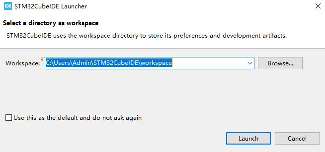
- Double-click the shortcut on the desktop to open STM32CubeIDE. You need to select a workspace and save it in another path (without Chinese) according to the actual situation.

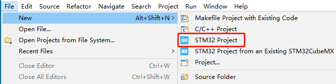
- Click File->New->STM32 Project.
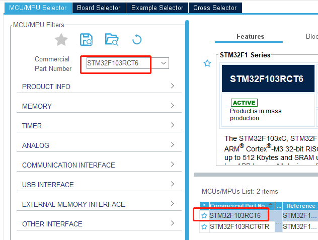
- Search and select chip STM32F103RCT6, then click Next in the lower right corner to go to the next step.
- Input the project name, take LED as an example here, other parameters can be used by default.

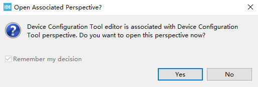
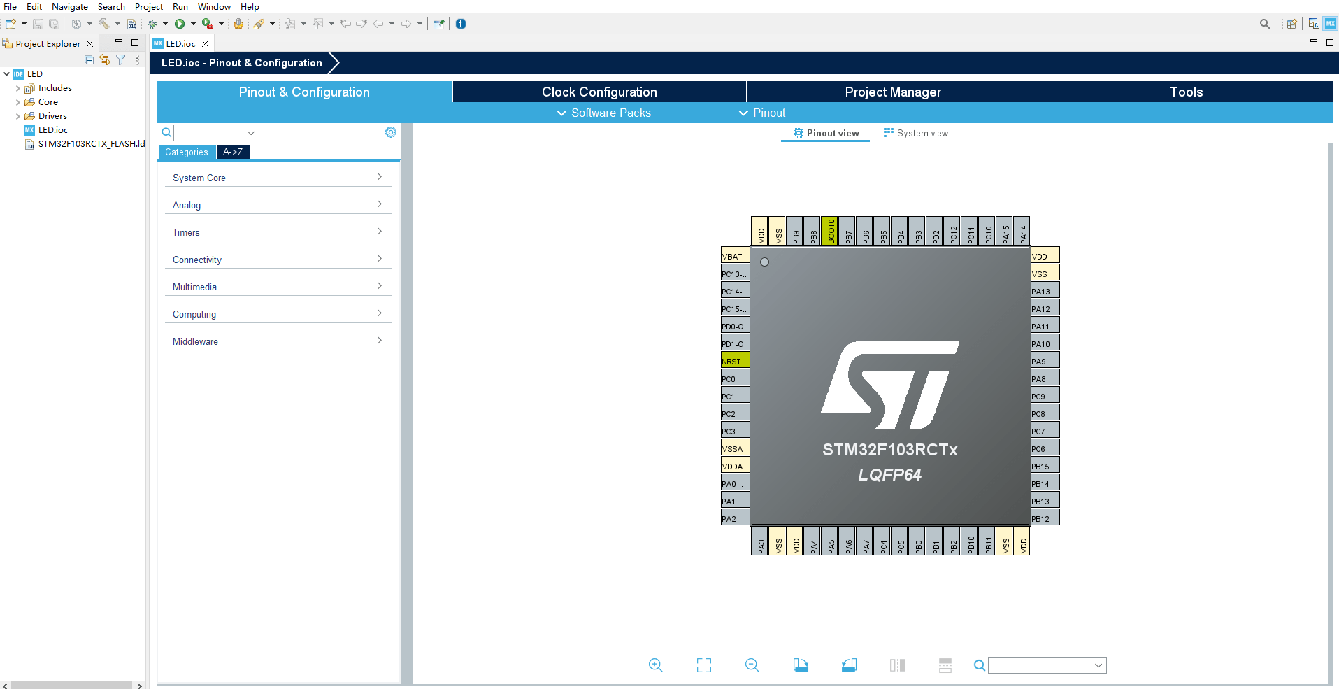
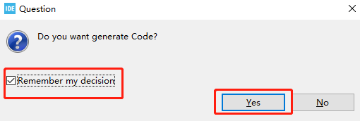
- Click Yes. The graphical content will be loaded.
After completion, it will be shown as follows:
2.5. Pin configuration
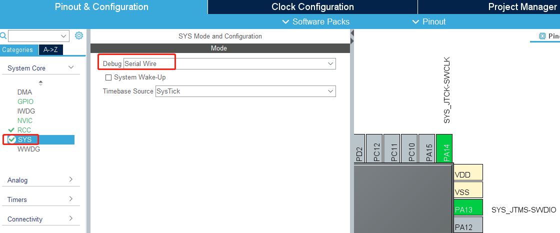
- First, you need Debug information. Under Pinout&Configuration, click SYS->Debug to select Serial Wire.
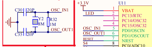
- Modify the system clock of STM32. According to the schematic diagram, the external crystal oscillator is 8M frequency.
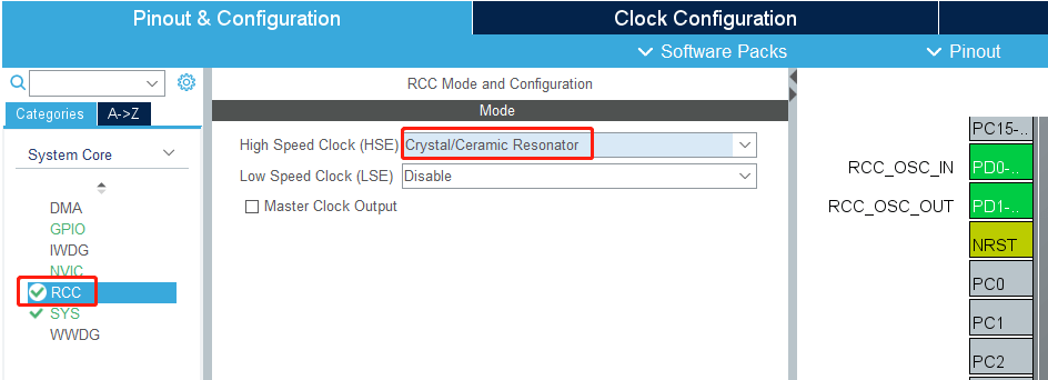
In Pin &Configuration select RCC->HSE select Crystal/Ceramic Resonator.HSE is the external clock, LSE is the internal clock, using the external clock can be more stable and efficient than the internal clock.
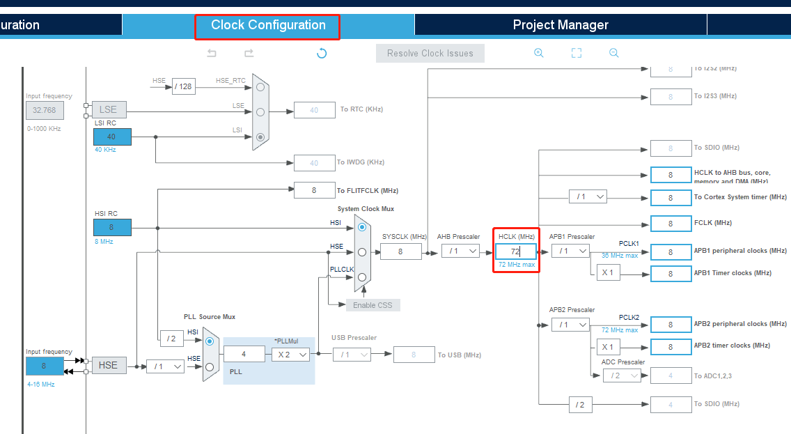
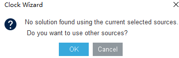
Switch to Clock Configuration to modify the frequency of HCLK to 72, and press Enter to confirm.
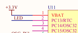
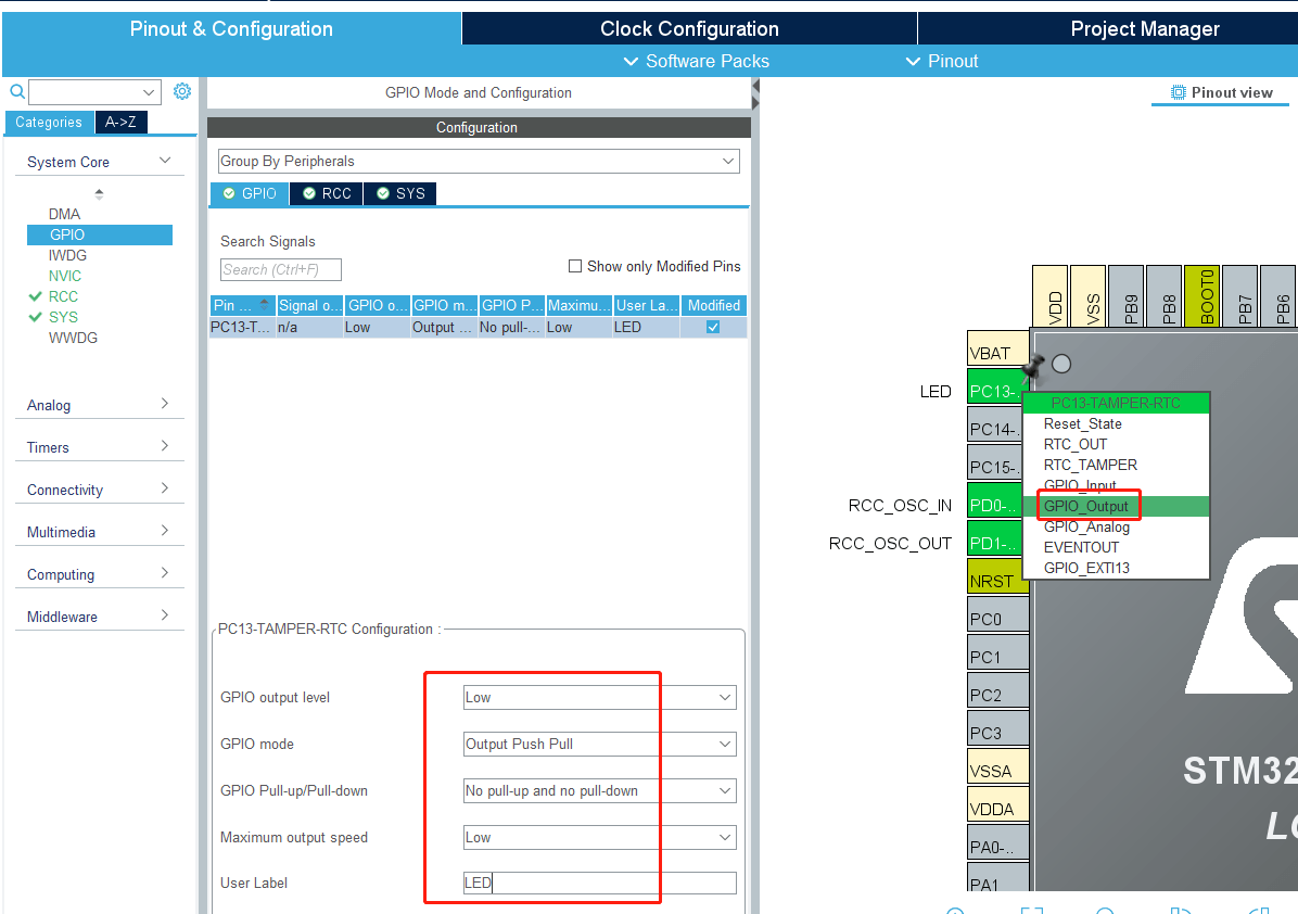
- Add the LED pin configuration. It can be seen from the schematic diagram that the LED is connected to the PC13 pin.
The PC13 pin is set to GPIO_Output in order to facilitate the change of Label to LED here.
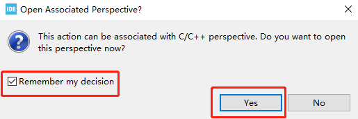
Then press Ctrl+S to save, check Remember my decision, and click Yes. This automatically generates code for each save.
2.6. Write code
- Since the previous graphical configuration has generated the initialization code of the system, we only need to add the functions to be implemented.
Find the main function in the main.c file and add the content to control the LED light under while (1). The function is the LED light flashes every 200 milliseconds. Press Ctrl+S to save the code.
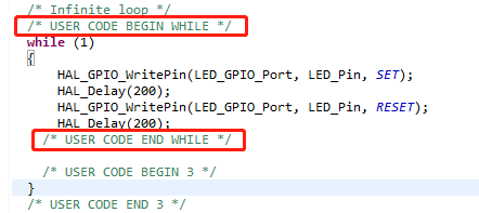
Note: CODE content needs to be added between USER CODE BEGIN and USER code END. Otherwise, the CODE content will be overwritten the next time the CODE is generated using the graphical tool. The content added between USER CODE BEGIN and USER code END will not be overwritten. Do not write Chinese comments in it, it may appear garbled.
2.7. Compiling programs
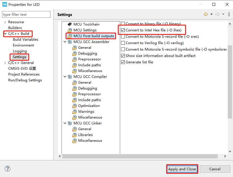
- Add the HEX file generation function.
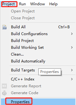
Click Project->Properties->C/C++ Build->Settings->MCU Post build outputs, then check before Convert to Intel Hex file(-o ihex), as shown below.
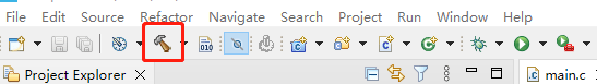
- Click the hammer in the toolbar to start compiling the project.
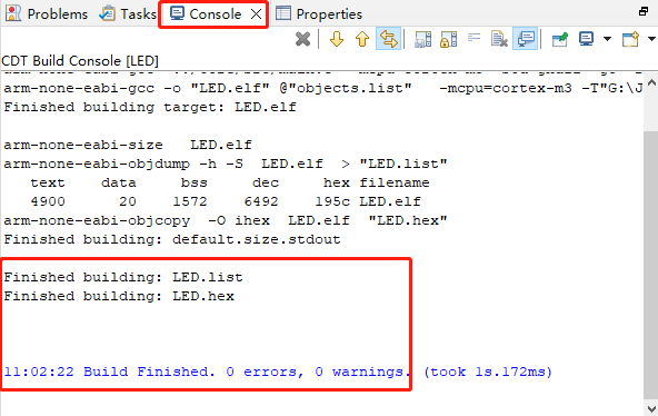
The STM32CubeIDE will pop up on the Console console and sees a compilation 0 error, with a 0 warning indicating that the compilation was successful. As shown below, the file generated by the project is named LED.hex and is saved in the Debug folder of the project directory.
2.8. SWD burn firmware
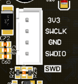
Follow the SWD interface on the ROS expansion board to connect to the ST-Link or J-Link debugger, power on and connect the debugger to the computer. The following uses connecting the ST-Link debugger as an example.
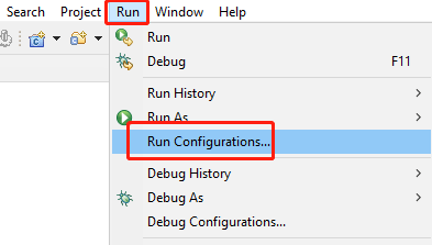
In the STM32CubeIDE menu bar, select Run->Debug Configurations.
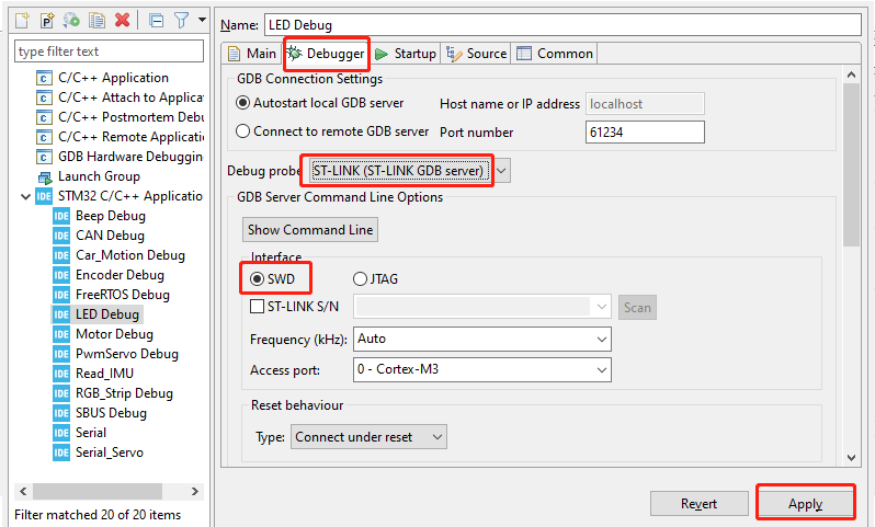
Choose Debugger >ST-LINK GDB server >SWD >Apply, save the data, and exit the configuration page.
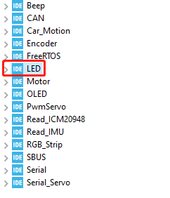
If there are multiple projects, first select the name of the program you want to run, for example, select LED project here.
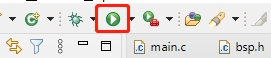
In the STM32CubeIDE menu bar, click the Run button to start burning the firmware.
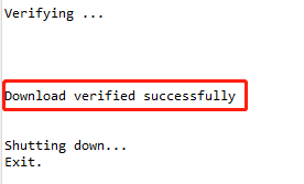
If the message "Download verified successfully" is displayed, the program is downloaded successfully.
2.9. ISP burn program
- Install the CH340 driver
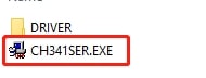
Since the USB communication of the ROS extension board uses the CH340 chip, the driver of the CH340 chip needs to be installed. If the computer has already installed the CH340 driver, it does not need to be installed again. Unzip the Uart drive (CH340).zip in the course materials, and double-click to open the CH341SER.EXE program
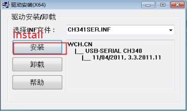
Click Install, after the installation is completed, the installation will be prompted to succeed.
- Download burning software
The mcuisp (or flymcu) burning software is required for burning the ROS expansion board MCU firmware. Please visit http://www.mcuisp.com to download the mcuisp (or flymcu) burning software. The mcuisp software provided in the documentation can also be used directly.
The mcuisp software is a green version that does not require installation and can be used by double-clicking.
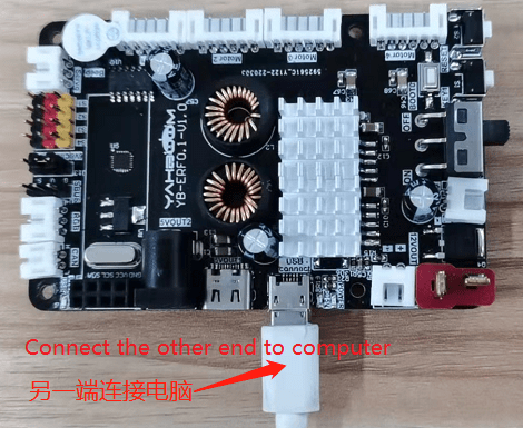
- Connect the device
Before connecting the ROS expansion board to your computer, unplug the Micro USB data cable and power cable connecting the Jetson Nano to the expansion board.
ROS
- Configure the burning software
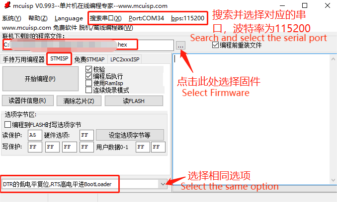
If multiple serial port numbers appear when searching for the serial port, you are not sure which one is the ROS expansion board. Solution 1: Unplug other USB ports and search; Solution 2: First unplug the USB data cable of the ROS expansion board, click Search serial port, record the serial port number found, insert the USB data cable of the ROS expansion board, search for the serial port again, compare before and after twice, the newly added serial port number is the serial port number of the ROS expansion board.
When selecting firmware, you need to select the LED.hex file in the Debug folder of the project directory.
The last is the configuration selection at the bottom, be sure to select the [low level reset of DTR, high level into the BootLoader of RTS] option, otherwise the download may fail.
- Burn program
Please first put the MCU on the expansion board into burning mode:
First hold down the BOOT0 key on the expansion board, then press the RESET key, and finally release the BOOT0 key.
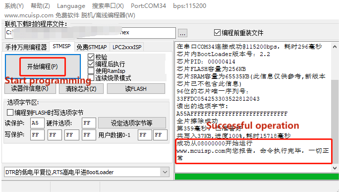
Click [Start programming], and the mcuisp burning software will burn the firmware we selected in the previous step to the MCU of the ROS expansion board.When the right 【 success from 08000000 began to run the www.mcuisp.com report to you, after command execution, everything was normal 】 tips download success. Note: ① Before starting to burn, please make sure that the serial port number of the ROS extension board is accessible, that is, no serial port assistant is occupying it. ② To enter the burning mode of ROS expansion board, press and hold the BOOT0 key on the expansion board first, then press the RESET key, and finally release the BOOT0 key.
2.10. Procedural phenomenon
The LED light on the expansion board flashes every 200 milliseconds.