Calibrate the IMU module
Calibrate the IMU module1. Accelerometer calibration2. Magnetic Field calibration3. Gyro stabilization4. Reset Height
Before performing the following operations, please confirm that the IMU module has been connected to the PC host computer software.
1. Accelerometer calibration
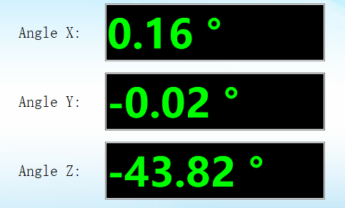
Place the IMU module flat on a table or other device, if you find that 'Angle X' and 'Angle Y' are greater than 1°, then accelerometer calibration is required.
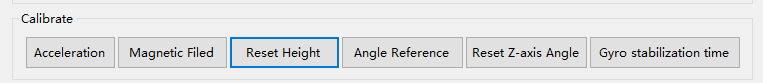
Click 'Config' in the menu bar to open the configuration interface, ensure that the IMU module is flat, click 'Acceleration', and then click ' Angle Reference'.
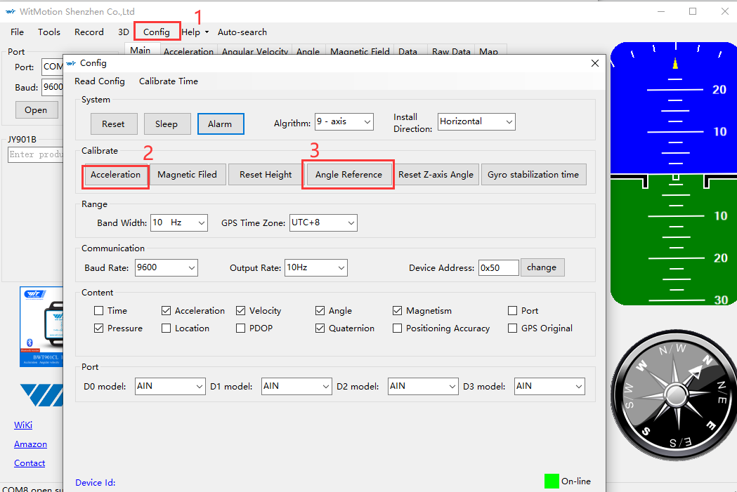
At this time, the 'angle X' and 'angle Y' of the main interface will be near 0°.
2. Magnetic Field calibration
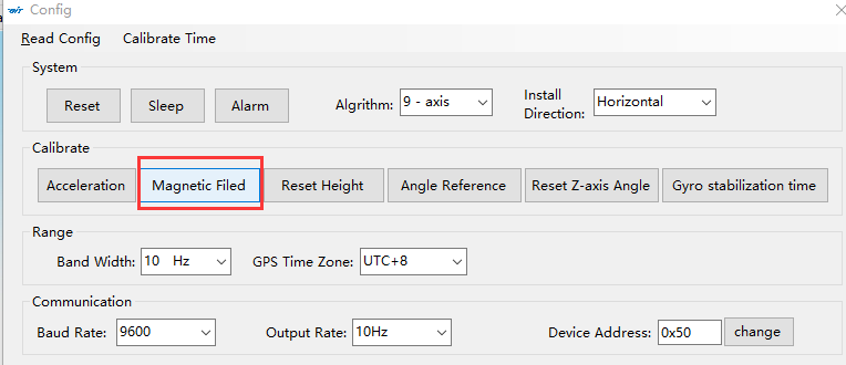
After the IMU module is powered on, turn on the host computer to display the 3D model, rotate the Z-axis heading angle of the module, the 3D model shakes, or the response is slow, please perform magnetic calibration on the PC host computer software.
Click 'Magnetic Field' in the configuration interface, and the interface for calibrating the magnetic field will pop up.
There are various calibration methods for magnetic field calibration, and the more conventional calibration method is the Ellipse fitting method.
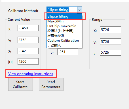
You can click 'View operating Instructions' to view the calibration steps. Calibration videos can also be viewed at the following URL.
https://www.bilibili.com/video/BV1YR4y1F7Ej?spm_id_from=333.337.search-card.all.click
Before starting the calibration, turn on your phone's compass and face north, or face south. Hold the IMU module suspended in the air in your hand.
Click 'Start Calibrate', wait for the initialization to complete and perform the following operations.
- Calibrate the Y-axis and watch the chartXZ change. Place the IMU module horizontally with the Y-axis perpendicular to the front of you. Then slowly rotate more than 360° around the Y axis, and the blue data distribution on the chartXZ interface is normal beside the green line. In order to make the data more accurate, turn it around a few more times.
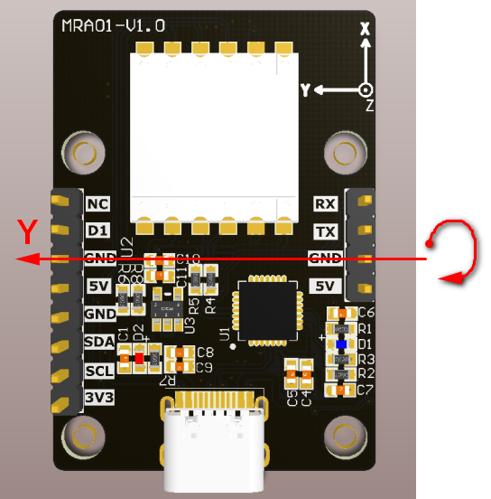
- Calibrate the X-axis and watch the chartYZ change. Place the IMU module horizontally, with the X-axis perpendicular to the front of you. Then slowly rotate more than 360° around the X-axis, and the blue data distribution on the chartYZ interface is normal beside the green line. In order to make the data more accurate, turn it around a few more times.
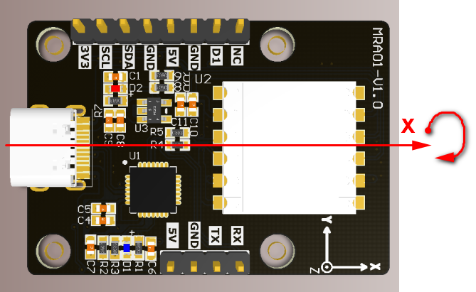
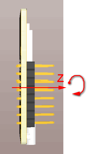
- Calibrate the z-axis and watch the chartXY change. Place the IMU module vertically with the Z axis perpendicular to the front of you. Then slowly rotate more than 360° around the Z axis, and the blue data on the chartXY interface is distributed next to the green line, which is normal. In order to make the data more accurate, turn it around a few more times.
- After all three axes of XYZ are calibrated, click 'Read Parameters'.
Note that when calibrating the Y-axis, just look at the data of chartXZ, and the other two views also have data, so you don't need to care. The same is true for the other two axes.
The following figure is a schematic diagram of the completion of the spherical fitting method to calibrate the magnetic field, for reference only:

3. Gyro stabilization
The auto-calibration function of the gyroscope is enabled by default, and no additional settings are required. Keep the "Gyro stabilization time" function turned on.
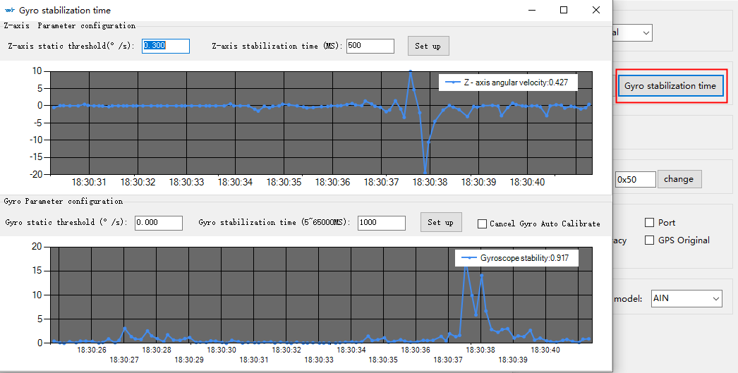
Gyro Parameter configuration: The gyro sensor usually has its own zero offset, such as 0.5°/s. When the sensor does not eliminate the zero offset, when outputting raw data, the angular velocity will always fluctuate within the range of 0.5°/s. Integrating the angle, the angle increases over time, causing the angle to drift. If you want to eliminate the angle drift phenomenon, you need to add gyroscope zero offset calibration to the sensor. The specific principle is to subtract the two adjacent angular velocity data before and after, and the obtained value is less than the set gyro static threshold and lasts for a period of time (gyro stabilization time) If it does not exceed this value, it is considered that the sensor is stationary. At this time, the zero offset calculation is started, and the average value of the angular velocity in one second is taken as the zero offset. The subsequent data will be subtracted from the zero offset value, and the sensor gyroscope data will return to zero.
Z-axis static threshold: After the Z-axis angular velocity (original angular velocity - zero offset) is less than the set Z-axis static threshold and lasts for the Z-axis stabilization time, the sensor will be considered static.
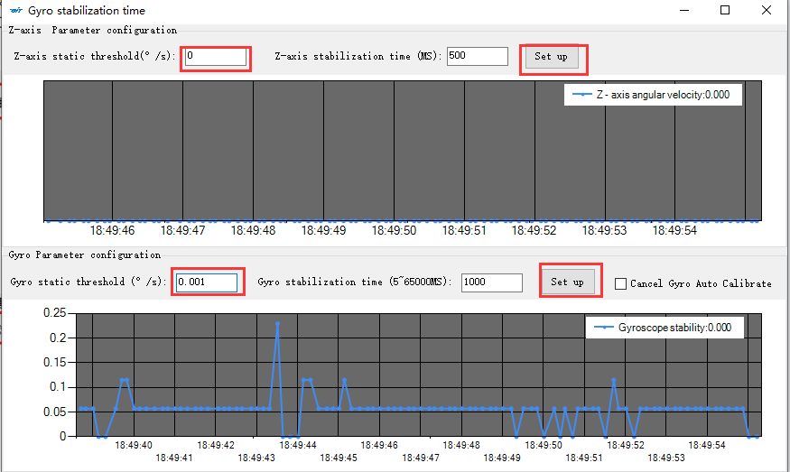
- If you need to turn off the automatic calibration function of the gyroscope, please change the Z-axis static threshold to 0, and the gyroscope static threshold to 0.001 (0.001 is the original data output by the sensor without zero offset calibration by default, and the stabilization time does not need to be changed, then Re-read the sensor data to confirm that the modification is successful and takes effect. After it takes effect, the automatic calibration function of the gyroscope is turned off.
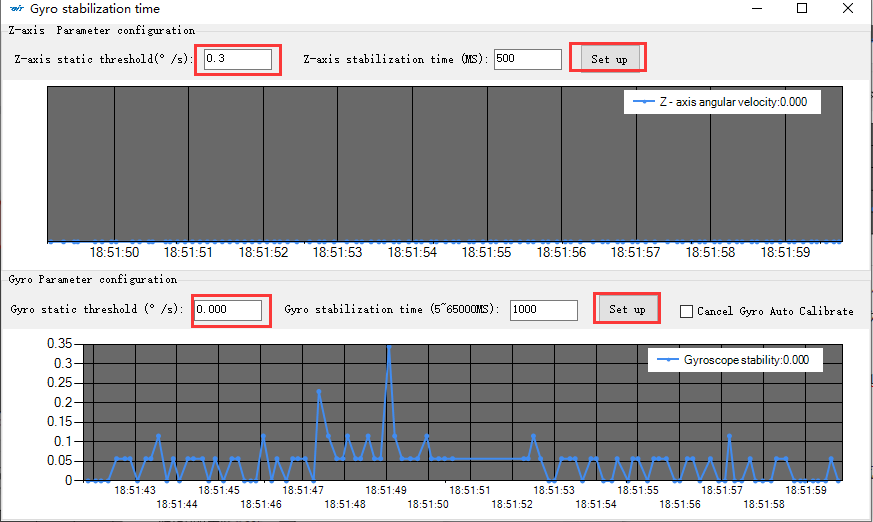
- When you want to use the automatic calibration function of the gyroscope, set the required static threshold (the default Z-axis static threshold is 0.3, and the gyroscope static threshold is 0.000). When the angular velocity data of the module exceeds the set value, it is considered that the sensor When it is moving, when it is less than the set value, the sensor is considered to be stationary.。
4. Reset Height
If the altitude data detected by the barometer is abnormal, the altitude needs to be calibrated. The barometer can only measure the approximate range and cannot measure the altitude accurately.
Before calibrating the altitude, please confirm that the ambient air pressure is gentle, and there should be no fan blowing to affect the calibration effect.
Click 'Config' - 'Reset Height' and wait for the calibration to complete.