6、Lidar mapping
6、Lidar mapping6.1、Instructions6.1.1、Mapping6.1.2、Usage6.1.3、Save map6.1.4、View info6.1.5、2D mapping by depth mapping alone6.2、Mapping algorithm6.2.1、gmapping1)Introduction2)Topics and services3)Configuration parameter4)TF Transforms6.2.2、hector1)Introduction2)Topics and services3)Parameters4)TF Transforms6.2.3、karto1)Introduction2)Topics and Services3)Parameters4)TF Transforms6.2.4、cartographer1)Introduction2)Code structure3)Parameters6.3、rrt_exploration6.3.1、Introduction6.3.2、global_rrt_frontier_detector1)Introduction2)Topics and Services3)Parameters6.3.3、local_rrt_frontier_detector1)Introduction2)Topics and Services3)Parameters6.3.4、frontier_opencv_detector1)Introduction2)Topics and Services3)Parameters6.3.5、filter1)Introduction2)Topics and Services3)Parameters6.3.6、Assigner1)Introduction2)Topics and Services3)Parameters
Gmapping:http://wiki.ros.org/gmapping/
hector_slam:http://wiki.ros.org/hector_slam
hector_slam/Tutorials:http://wiki.ros.org/hector_slam/Tutorials/SettingUpForYourRobot
hector_mapping:http://wiki.ros.org/hector_mapping
karto:http://wiki.ros.org/slam_karto
Cartographer:https://google-cartographer.readthedocs.io/en/latest/
Cartographer ROS:https://google-cartographer-ros.readthedocs.io/en/latest/
rrt_exploration:http://wiki.ros.org/rrt_exploration
rrt_exploration/Tutorials:http://wiki.ros.org/rrt_exploration/Tutorials
map_server:https://wiki.ros.org/map_server
6.1、Instructions
6.1.1、Mapping
Note: When building a map, the slower the speed of the car, the better the effect (especially the rotation speed). If the speed is too fast, the effect will be poor.
Start command (note: the navigation effect of depth mapping alone is not good, so it is not recommended).
roslaunch transbot_nav usbcam_bringup.launch # mono + laser + Transbotroslaunch transbot_nav astra_bringup.launch # Astra + Transbotroslaunch transbot_nav laser_bringup.launch # laser + Transbotroslaunch transbot_nav transbot_bringup.launch # Astra + laser + TransbotMapping
xxxxxxxxxxroslaunch transbot_nav transbot_map.launch map_type:=gmapping roslaunch transbot_nav transbot_map.launch map_type:=hectorroslaunch transbot_nav transbot_map.launch map_type:=kartoroslaunch transbot_nav transbot_map.launch map_type:=cartographerroslaunch transbot_nav rrt_exploration.launch - Parameter 【map_type】: mapping algorithm 【gmapping,hector,karto,cartographer】, the default is 【gmapping】.
6.1.2、Usage
Run following command, then you can control robot movement by keyboard
xxxxxxxxxxrosrun teleop_twist_keyboard teleop_twist_keyboard.py # system integrationroslaunch transbot_ctrl transbot_keyboard.launch # customizeOr you can control robot by handle, no need run any code. The command for mapping or navigation includes the start command for the handle control.
We need to make sure that the robot walks all over the area to be mapped. As shown below, the map should be closed.
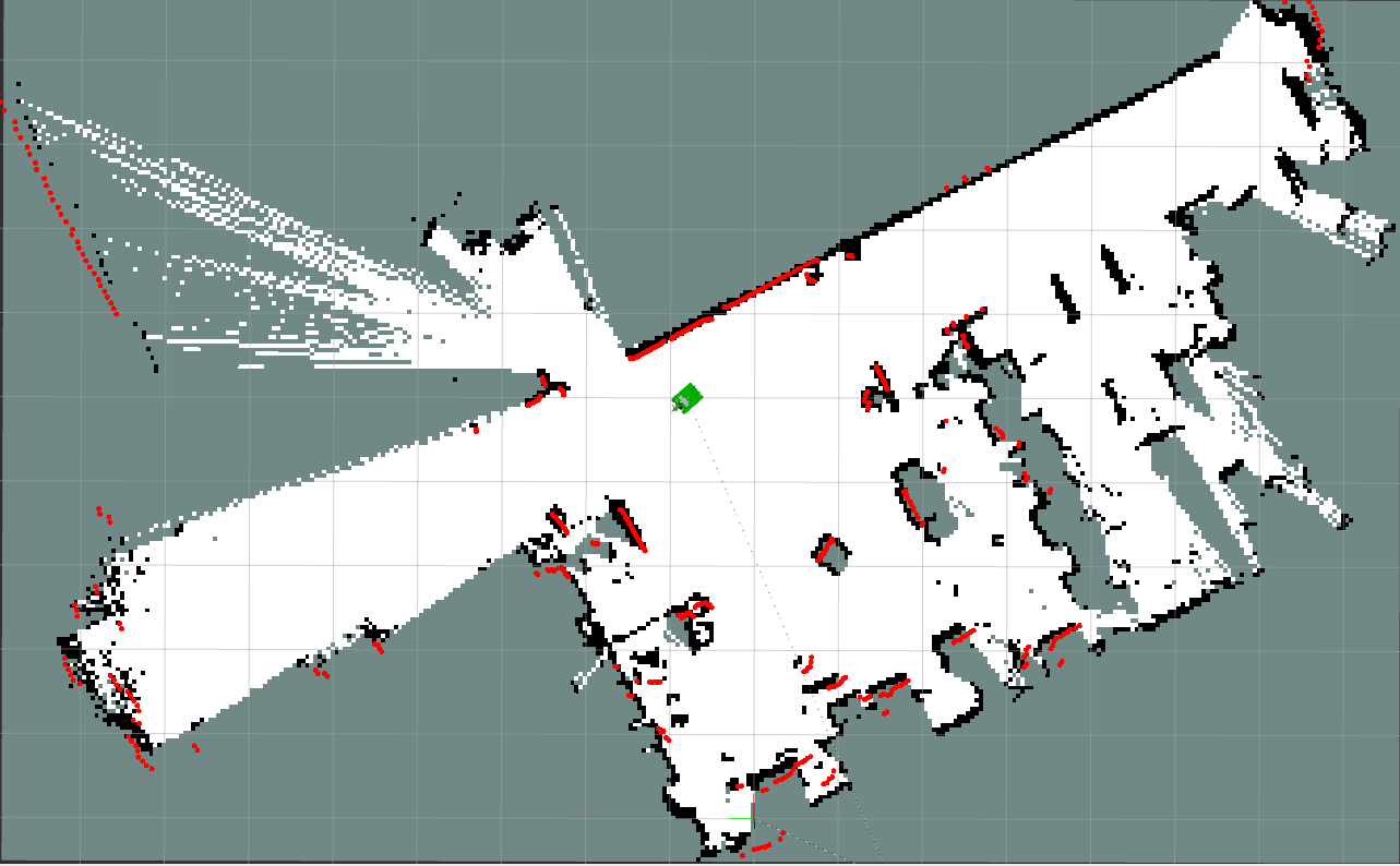
There may be some scattered points during the mapping process. If the mapping environment is well closed, relatively regular, and the movement speed is slower, the scattering phenomenon will be much smaller.
6.1.3、Save map
There are different ways of saving maps in several mapping algorithms.
cartographer:execute the following command
xxxxxxxxxxbash ~/transbot_ws/src/transbot_nav/maps/carto_map.shrrt_exploration:After selecting five points as required, the robot begins to explore and build maps. After the map is created, the system will automatically save the map and return to the zero point. The map is saved to this path: ~/transbot_ws/src/transbot_nav/maps/my_map,file name is rrt_map.
gmapping,hector,karto:execute the following command to save file
xxxxxxxxxxrosrun map_server map_saver -f ~/transbot_ws/src/transbot_nav/maps/my_map # Method 1bash ~/transbot_ws/src/transbot_nav/maps/map.sh # Method 2The map is saved to this path: ~/transbot_ws/src/transbot_nav/maps/,a pgm picture file and a yaml file.
map.yaml
xxxxxxxxxximage: map.pgmresolution: 0.05 origin: [-15.4,-12.2,0.0] negate: 0occupied_thresh: 0.65free_thresh: 0.196Parameter analysis:
- image: The path of the map file, which can be an absolute path or a relative path.
- resolution: the resolution of the map, m/pixel
- origin: The 2D pose (x,y,yaw) in the lower left corner of the map, where yaw is rotated counterclockwise (yaw=0 means no rotation). Many parts of the current system ignore the yaw value.
- negate: whether to reverse the meaning of white/black and free/occupied (the interpretation of the threshold is not affected)
- Occupied_thresh: Pixels with occupation probability greater than this threshold will be considered as fully occupied.
- free_thresh: Pixels whose occupancy probability is less than this threshold will be considered completely free.
6.1.4、View info
View tf tree
xxxxxxxxxxrosrun rqt_tf_tree rqt_tf_tree
View node
xxxxxxxxxxrqt_graph
6.1.5、2D mapping by depth mapping alone
Start the driver reference【6.1.1】# Astra + Transbot; the command for starting the map is the same as【6.1.1】.
The function package depthimage_to_laserscan is mainly used to convert the depth image into lidar data. Its mapping function is the same as that of lidar.
Note: The scanning range of the depth camera is not 360°.
xxxxxxxxxxrqt_graph

6.2、Mapping algorithm
6.2.1、gmapping
1)Introduction
- Gmapping is a commonly used open source SLAM algorithm based on the filtering SLAM framework.
- Gmapping is based on the RBpf particle filter algorithm, which separates the positioning and mapping process, and performs positioning before mapping.
- Gmapping has made two major improvements to the RBpf algorithm: improved proposal distribution and selective resampling.
Advantages: Gmapping can construct indoor maps in real time, and the amount of calculation required to construct small scene maps is small and the accuracy is high.
Disadvantages: Not suitable for building large scene maps.
2)Topics and services
| Subscribe to topics | Type | Description |
|---|---|---|
| tf | tf/tfMessage | Used for conversion between lidar coordinate system, base coordinate system and odometer coordinate system |
| scan | sensor_msgs/LaserScan | Lidar scan data |
| Topic | Type | Description |
| map_metadata | nav_msgs/MapMetaData | Publish map Meta data |
| map | nav_msgs/OccupancyGrid | Publish map raster data |
| ~entropy | std_msgs/Float64 | Release the estimation of robot pose distribution entropy |
| Service | Type | Description |
| dynamic_map | nav_msgs/GetMap | Get map data |
3)Configuration parameter
| Parameter | Type | Defaults value | Description |
|---|---|---|---|
| ~throttle_scans | int | 1 | Process 1 out of every this many scans (set it to a higher number to skip more scans) |
| ~base_frame | string | "base_link" | The frame attached to the mobile base. |
| ~map_frame | string | "map" | The frame attached to the map. |
| ~odom_frame | string | "odom" | The frame attached to the odometry system. |
| ~map_update_interval | float | 5.0 | How long (in seconds) between updates to the map. Lowering this number updates the occupancy grid more often, at the expense of greater computational load. |
| ~maxUrange | float | 80.0 | The maximum usable range of the laser. A beam is cropped to this value. |
| ~sigma | float | 0.05 | The sigma used by the greedy endpoint matching |
| ~kernelSize | int | 1 | The kernel in which to look for a correspondence |
| ~lstep | float | 0.05 | The optimization step in translation |
| ~astep | float | 0.05 | The optimization step in rotation |
| ~iterations | int | 5 | The number of iterations of the scanmatcher |
| ~lsigma | float | 0.075 | The sigma of a beam used for likelihood computation |
| ~ogain | float | 3.0 | Gain to be used while evaluating the likelihood, for smoothing the resampling effects |
| ~lskip | int | 0 | Number of beams to skip in each scan. |
| ~minimumScore | float | 0 | Minimum score for considering the outcome of the scan matching good. Can avoid jumping pose estimates in large open spaces when using laser scanners with limited range (e.g. 5m). Scores go up to 600+, try 50 for example when experiencing jumping estimate issues. |
| ~srr | float | 0.1 | Odometry error in translation as a function of translation (rho/rho) |
| ~srt | float | 0.2 | Odometry error in translation as a function of rotation (rho/theta) |
| ~str | float | 0.1 | Odometry error in rotation as a function of translation (theta/rho) |
| ~stt | float | 0.2 | Odometry error in rotation as a function of rotation (theta/theta) |
| ~linearUpdate | float | 1.0 | Process a scan each time the robot translates this far |
| ~angularUpdate | float | 0.5 | Process a scan each time the robot rotates this far |
| ~temporalUpdate | float | -1.0 | Process a scan if the last scan processed is older than the update time in seconds. A value less than zero will turn time based updates off. |
| ~resampleThreshold | float | 0.5 | The Neff based resampling threshold |
| ~particles | int | 30 | Number of particles in the filter |
| ~xmin | float | -100.0 | Initial minimum size of the map in x direction |
| ~ymin | float | -100.0 | Initial minimum size of the map in y direction |
| ~xmax | float | 100.0 | Initial maximum size of the map in x direction |
| ~ymax | float | 100.0 | Initial maximum size of the map in y direction |
| ~delta | float | 0.05 | Resolution of the map (in metres per occupancy grid block) |
| ~llsamplerange | float | 0.01 | Translational sampling range for the likelihood |
| ~llsamplestep | float | 0.01 | Translational sampling step for the likelihood |
| ~lasamplerange | float | 0.005 | Angular sampling range for the likelihood |
| ~lasamplestep | float | 0.005 | Angular sampling step for the likelihood |
| ~transform_publish_period | float | 0.05 | How long (in seconds) between transform publications. |
| ~occ_threh | float | 0.25 | Threshold on gmapping's occupancy values |
| ~maxRange(float) | float | - | Threshold on gmapping's occupancy values |
4)TF Transforms
| Required tf Transforms TF | Description |
|---|---|
| laser-->base_link | sually a fixed value, broadcast periodically by a robot_state_publisher, or a tf static_transform_publisher. |
| base_link-->odom | usually provided by the odometry system (e.g., the driver for the mobile base) |
| Provided tf Transforms | Description |
| map-->odom | the current estimate of the robot's pose within the map frame |
6.2.2、hector
1)Introduction
Features: hector_slam does not need to subscribe to the odometer/odom message, uses the Gauss Newton method, and directly uses the lidar to estimate the odometer information. However, when the robot speed is faster, it will cause deviations in the mapping effect, and the requirements for sensors are high.
When building maps, adjust the rotation speed of the trolley as low as possible.
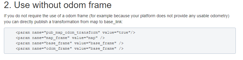
There is no way to use the odom coordinate system, which is taken from the Wiki.
2)Topics and services
| Topic subscription | Type | Description |
|---|---|---|
| scan | sensor_msgs/LaserScan | The laser scan used by the SLAM system. |
| syscommand | std_msgs/String | System command. If the string equals "reset" the map and robot pose are reset to their inital state. |
| Published Topics | Type | Description |
| map_metadata | nav_msgs/MapMetaData | Get the map data from this topic |
| map | nav_msgs/OccupancyGrid | Get the map data from this topic |
| slam_out_pose | geometry_msgs/PoseStamped | The estimated robot pose without covariance |
| poseupdate | geometry_msgs /PoseWithCovarianceStamped | The estimated robot pose with an gaussian estimate of uncertainty |
| Services | Type | Description |
| dynamic_map | nav_msgs/GetMap | Call this service to get the map data. |
| reset_map | std_srvs/Trigger | Call this service to reset the map, and hector will start a whole new map from scratch. Notice that this doesn't restart the robot's pose, and it will restart from the last recorded pose. |
| pause_mapping | std_srvs/SetBool | Call this service to stop/start processing laser scans. |
| restart_mapping_with_new_pose | hector_mapping/ResetMapping | Call this service to reset the map, the robot's pose, and resume mapping (if paused) |
3)Parameters
| Parameters | Type | Defaults value | Description |
|---|---|---|---|
| ~base_frame | String | "base_link" | The name of the base frame of the robot. This is the frame used for localization and for transformation of laser scan data. |
| ~map_frame | String | "map" | The name of the map frame. |
| ~odom_frame | string | "odom" | The name of the odom frame. |
| ~map_resolution | Double | 0.025(m) | The map resolution [m]. This is the length of a grid cell edge. |
| ~map_size | Int | 1024 | The size of the map. |
| ~map_start_x | double | 0.5 | Location of the origin [0.0, 1.0] of the /map frame on the x axis relative to the grid map. 0.5 is in the middle. |
| ~map_start_y | double | 0.5 | Location of the origin [0.0, 1.0] of the /map frame on the y axis relative to the grid map. 0.5 is in the middle. |
| ~map_update_distance_thresh | double | 0.4(m) | Threshold for performing map updates [m]. The platform has to travel this far in meters or experience an angular change as described by the map_update_angle_thresh parameter since the last update before a map update happens. |
| ~map_update_angle_thresh | double | 0.9(rad) | Threshold for performing map updates [rad]. The platform has to experience an angular change as described by this parameter of travel as far as specified by the map_update_distance_thresh parameter since the last update before a map update happens. |
| ~map_pub_period | double | 2.0 | The map publish period [s]. |
| ~map_multi_res_levels | int | 3 | The number of map multi-resolution grid levels. |
| ~update_factor_free | double | 0.4 | The map update modifier for updates of free cells in the range [0.0, 1.0]. |
| ~update_factor_occupied | double | 0.9 | The map update modifier for updates of occupied cells in the range [0.0, 1.0]. |
| ~laser_min_dist | double | 0.4(m) | The minimum distance [m] for laser scan endpoints to be used by the system. |
| ~laser_max_dist | double | 30.0(m) | The maximum distance [m] for laser scan endpoints to be used by the system |
| ~laser_z_min_value | double | -1.0(m) | The minimum height [m] relative to the laser scanner frame for laser scan endpoints to be used by the system. |
| ~laser_z_max_value | double | 1.0(m) | The maximum height [m] relative to the laser scanner frame for laser scan endpoints to be used by the system. |
| ~pub_map_odom_transform | bool | true | Determine if the map->odom transform should be published by the system. |
| ~output_timing | bool | false | Output timing information for processing of every laser scan via ROS_INFO. |
| ~scan_subscrible_queue_size | int | 5 | The queue size of the scan subscriber. |
| ~pub_map_scanmatch_transform | bool | true | Determines if the scanmatcher to map transform should be published to tf. |
| ~tf_map_scanmatch_transform_frame_name | String | "scanmatcher_frame" | The frame name when publishing the scanmatcher to map transform as described in the preceding parameter. |
4)TF Transforms
| Required tf Transforms | Description |
|---|---|
| laser-->base_link | usually a fixed value, broadcast periodically by a robot_state_publisher, or a tf static_transform_publisher. |
| Provided tf Transforms | Description |
| map-->odom | the current estimate of the robot's pose within the map frame (only provided if parameter "pub_map_odom_transform" is true). |
6.2.3、karto
1)Introduction
Karto is a 2D laser SLAM solution, which is based on a sparse graph optimization method with closed loop detection. Karto uses the spa (karto_slam) or g2o (nav2d) optimization library, and the front-end and back-end uses a single-threaded process. It uses odom to predict the initial position.
2)Topics and Services
| Subscribed Topics | Type | Description |
|---|---|---|
| scan | sensor_msgs/LaserScan | Transforms necessary to relate frames for laser, base, and odometry |
| tf | tf/tfMessage | Laser scans to create the map from |
| Published Topics | Type | Description |
| map_metadata | nav_msgs/MapMetaData | Get the metadata of the map data (resolution, width, height, ...) |
| map | nav_msgs/OccupancyGrid | Get the map data from this topic, which is latched, and updated periodically |
| visualization_marker_array | visualisation_msgs / MarkerArray | Get the pose graph from this topic, which is updated periodically |
| Published Topics | Type | Description |
| dynamic_map | nav_msgs/GetMap | Call this service to get the map data |
3)Parameters
- General parameters
| Parameters | Type | Defaults value | Description |
|---|---|---|---|
| ~base_frame | string | "base_link" | The frame attached to the mobile base. |
| ~map_frame | string | "map" | The frame attached to the map. |
| ~odom_frame | string | "odom" | The frame attached to the odometry system. |
| ~throttle_scans | int | 1 | Process 1 out of every this many scans (set it to a higher number to skip more scans) |
| ~map_update_interval | float | 5.0 | How long (in seconds) between updates to the map. Lowering this number updates the occupancy grid more often, at the expense of greater computational load. |
| ~resolution | float | 0.05 | Resolution of the map (in metres per occupancy grid block) |
| ~delta | float | 0.05 | Resolution of the map (in metres per occupancy grid block). Same as resolution. Defined for compatibility with the parameter names of gmapping. |
| ~transform_publish_period | float | 0.05 | How long (in seconds) between transform publications. To disable broadcasting transforms, set to 0. |
| use_scan_matching | bool | true | When set to true, the mapper will use a scan matching algorithm. In most real-world situations this should be set to true so that the mapper algorithm can correct for noise and errors in odometry and scan data. In some simulator environments where the simulated scan and odometry data are very accurate, the scan matching algorithm can produce worse results. In those cases set this to false to improve results. |
| use_scan_barycenter | bool | true | Use the barycenter of scan endpoints to define distances between scans. |
| minimum_travel_distance | double | 0.2 | Sets the minimum travel between scans. |
| minimum_travel_heading | double | deg2rad(10)=0.087266461 | Sets the minimum heading change between scans |
| scan_buffer_size | int | 70 | Sets the length of the scan chain stored for scan matching. scan_buffer_size should be set to approximately scan_buffer_maximum_scan_distance / minimum_travel_distance. |
| scan_buffer_maximum_scan_distance | double | 20.0 | Sets the maximum distance between the first and last scans in the scan chain stored for matching. |
| link_match_minimum_response_fine | double | 0.8 | Scans are linked only if the correlation response value is greater than this value. |
| link_scan_minimum_distance | double | 10.0 | Sets the maximum distance between linked scans. Scans that are farther apart will not be linked regardless of the correlation response value. |
| loop_search_maximum_distance | double | 4.0 | Scans less than this distance from the current position will be considered for a match in loop closure. |
| do_loop_closing | bool | true | Enable/disable loop closure. |
| loop_match_minimum_chain_size | int | 10 | When the loop closure detection finds a candidate it must be part of a large set of linked scans |
| loop_match_maximum_variance_coarse | double | math::Square(0.4)=0.16 | The co-variance values for a possible loop closure have to be less than this value to consider a viable solution. This applies to the coarse search. |
| loop_match_minimum_response_coarse | double | 0.8 | If response is larger than this, then initiate loop closure search at the coarse resolution. |
| loop_match_minimum_response_fine | double | 0.8 | If response is larger than this, then initiate loop closure search at the fine resolution. |
- Correction parameters
| Parameters | Type | Defaults value | Description |
|---|---|---|---|
| correlation_search_space_dimension | double | 0.3 | Sets the size of the search grid used by the matcher. |
| correlation_search_space_resolution | double | 0.01 | Sets the resolution (size of a grid cell) of the correlation grid. |
| correlation_search_space_smear_deviation | double | 0.03 | The point readings are smeared by this value in X and Y to create a smoother response. |
- Loopback parameters
| Parameters | Type | Defaults value | Description |
|---|---|---|---|
| loop_search_space_dimension | double | 8.0 | The size of the search grid used by the matcher. |
| loop_search_space_resolution | double | 0.05 | The resolution (size of a grid cell) of the correlation grid. |
| loop_search_space_smear_deviation | double | 0.03 | The point readings are smeared by this value in X and Y to create a smoother response. |
- Scan Matcher parameters
| Parameters | Type | Defaults value | Description |
|---|---|---|---|
| distance_variance_penalty | double | sqrt(0.3)=0.09(<1.0) | Variance of penalty for deviating from odometry when scan-matching. The penalty is a multiplier (less than 1.0) is a function of the delta of the scan position being tested and the odometric pose. |
| angle_variance_penalty | double | sqrt(deg2rad(20))=0.17453292 | See distance_variance_penalty. |
| fine_search_angle_offset | double | deg2rad(0.2)=0.0017453292 | The range of angles to search during a fine search. |
| coarse_search_angle_offset | double | deg2rad(20)=0.17453292 | The range of angles to search during a coarse search. |
| coarse_angle_resolution | double | deg2rad(2)=0.017453292 | Resolution of angles to search during a coarse search. |
| minimum_angle_penalty | double | 0.9 | Minimum value of the angle penalty multiplier so scores do not become too small. |
| minimum_distance_penalty | double | 0.5 | Minimum value of the distance penalty multiplier so scores do not become too small. |
| use_response_expansion | bool | false | Whether to increase the search space if no good matches are initially found |
4)TF Transforms
| Required tf Transforms | Description |
|---|---|
| laser-->base_link | usually a fixed value, broadcast periodically by a robot_state_publisher, or a tf static_transform_publisher. |
| base_link-->odom | usually provided by the odometry system (e.g., the driver for the mobile base) |
| Provided tf TransformsTF | Description |
| map-->odom | the current estimate of the robot's pose within the map frame |
6.2.4、cartographer
1)Introduction
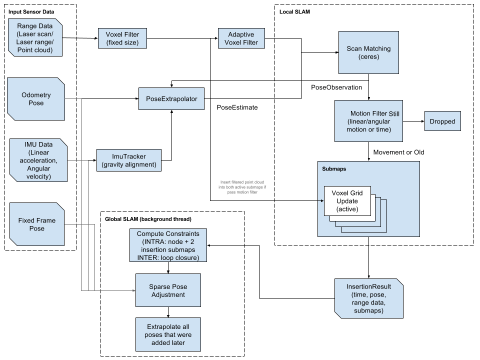
Cartographer is a 2D and 3D SLAM (simultaneous localization and mapping) library supported by a ROS system open sourced by Google. A graph-building algorithm based on graph optimization (multi-threaded back-end optimization, problem optimization built by cere). Data from multiple sensors (for example, LIDAR, IMU, and camera) can be combined to calculate the position of the sensor simultaneously and map the environment around the sensor.
2)Code structure
The source code of cartographer mainly includes three parts: cartographer、cartographer_ros and ceres-solver 。
- cartographer
- cartographer_ros
The package cartographer_ros runs in the ROS system. It can receive various sensor data in the form of ROS messages, and publish it in the form of messages after processing, which is convenient for debugging and visualization.
3)Parameters
lua file
| Parameters | Description |
|---|---|
| map_frame | Map coordinate system |
| tracking_frame | Convert all sensor data to this coordinate system |
| published_frame | The map points to coordinate system the |
| odom_frame | If true, the tf tree is map->odom->footprint; if false, the tf tree is map->footprint |
| provide_odom_frame | If true, the local, non-loop-closed, continuous pose will be published as odom_frame in map_frame |
| publish_frame_projected_to_2d | If enabled, the published pose will restrict 2D poses |
| use_odometry | Whether to use the odometer, if you use it, you must have odom tf |
| use_nav_sat | Whether to use gps |
| use_landmarks | Whether to use landmark |
| num_laser_scans | Whether to use single-line laser data |
| num_multi_echo_laser_scans | Whether to use multi_echo_laser_scans data |
| num_subdivisions_per_laser_scan | 1 frame of data is divided into several processings, in generally it is 1 |
| num_point_clouds | Whether to use point cloud data |
| lookup_transform_timeout_sec | Find the timeout of tf |
| submap_publish_period_sec | Time interval for publishing submap (seconds) |
| pose_publish_period_sec | The time interval for posting pose, when the value is 5e-3, it is 200HZ |
| trajectory_publish_period_sec | The time interval for publishing trajectory markers (trajectory nodes), the value is 30e-3 to 30ms |
| rangefinder_sampling_ratio | Fixed sampling frequency of lidar messages |
| odometry_sampling_ratio | Fixed sampling frequency of odometer messages |
| fixed_frame_pose_sampling_ratio | Fixed sampling frequency of fixed coordinate system messages |
| imu_sampling_ratio | Fixed sampling frequency of IMU messages |
| landmarks_sampling_ratio | Fixed sampling frequency for road sign messages |
6.3、rrt_exploration
6.3.1、Introduction
RRT exploration is a search algorithm based on the RRT path planning algorithm.
RRT algorithm is as follows:
- Global RRT frontier point detector node.
- Local RRT frontier point detector node.
- OpenCV-based frontier detector node.
- Filter node.
- Assigner node.
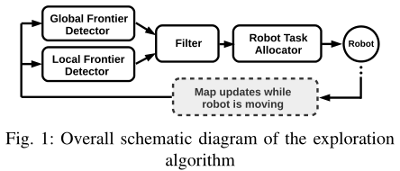
There are 3 types of nodes: nodes used to detect boundary points occupying the grid map, nodes used to filter detected points, and nodes used to assign points to robots.
6.3.2、global_rrt_frontier_detector
1)Introduction
The global_rrt_frontier_detector node uses the occupancy grid and finds boundary points (that is, exploration targets) in it. It publishes the detected points so that the filter nodes can process them. In a multi-robot configuration, only one instance of this node is run.
2)Topics and Services
| Subscribed Topics | Type | Description |
|---|---|---|
| map | nav_msgs/OccupancyGrid | The topic name is defined by the ~map_Topic parameter. It is the name of the topic that the node receives. |
| clicked_point | geometry_msgs/PointStamped | The area to be detected by the global_rrt_frontier_detector node. This topic is where the node receives the five points that define the area. The first four points are the four points that define the square area to be explored, and the last point is the starting point of the tree. After the announcement of these five points, the RRT will begin to detect border points. |
| Published Topics | Type | Description |
| detected_points | geometry_msgs/PointStamped | Post the topic of the detected boundary point. |
| shapes | visualization_msgs/Marker | Publish RRT hypothetical line type to view with Rviz. |
3)Parameters
| Parameters | Type | Defaults value | Description |
|---|---|---|---|
| ~map_topic | string | "/robot_1/map" | The node receives the map topic mapping name |
| ~eta | float | 5.0 | This parameter controls the growth rate of RRT used to detect boundary points, in meters. |
6.3.3、local_rrt_frontier_detector
1)Introduction
This node is similar to global_rrt_frontier_detector. However, it works differently, because every time a boundary point is detected, the tree here is constantly reset. This node will run along the global boundary detector node, which is responsible for quickly detecting boundary points located near the robot.
2)Topics and Services
| Subscribed Topics | Type | Description |
|---|---|---|
| map | nav_msgs/OccupancyGrid | The name of the map topic subscribed by this node. |
| clicked_point | geometry_msgs/PointStamped | Similar to the global_rrt_frontier_detector node |
| Published Topics | Type | Description |
| detected_points | geometry_msgs/PointStamped | Post the topic of the detected boundary point. |
| shapes | visualization_msgs/Marker | Publish RRT hypothetical line type to view with Rviz. |
3)Parameters
| Parameters | Type | Defaults value | Description |
|---|---|---|---|
| ~/robot_1/base_link | string | "/robot_1/base_link" | Connect to the frame of the robot. Each time the RRT tree is reset, it will start from the current robot position obtained in this coordinate system. |
| ~map_topic | string | "/robot_1/map" | The node receives the map topic mapping name |
| ~eta | float | 5.0 | This parameter controls the growth rate of RRT used to detect boundary points, in meters. |
6.3.4、frontier_opencv_detector
1)Introduction
This node is another boundary detector, but it is not based on RRT.
2)Topics and Services
| Subscribed Topics | Type | Description |
|---|---|---|
| map | nav_msgs/OccupancyGrid | The name of the map topic subscribed by this node. |
| Published Topics | Type | Description |
| detected_points | geometry_msgs/PointStamped | Post the topic of the detected boundary point. |
| shapes | visualization_msgs/Marker | Publish RRT hypothetical line type to view with Rviz. |
3)Parameters
| Parameters | Type | Defaults value | Description |
|---|---|---|---|
| ~map_topic | string | "/robot_1/map" | The node receives the map topic mapping name |
6.3.5、filter
1)Introduction
The node node receives the detected boundary points from all detectors, filters these points, and passes them to the distribution node to command the robot. Filtering includes deleting old points and invalid points, as well as deleting redundant points.
2)Topics and Services
| Subscribed Topics | Type | Description |
|---|---|---|
| map | nav_msgs/OccupancyGrid | The topic name is defined by the ~map_Topic parameter. It is the name of the topic that the node receives. |
| robot_x/move_base_node /global_costmap/costmap | nav_msgs/OccupancyGrid | x is the number of the robot. This node subscribes to the topics of all cost maps of all robots, so costmap is needed. |
| detected_points | geometry_msgs/PointStamped | The name of the topic defined by ~goals_topic. It is the topic of the filter node receiving boundary detection points. |
| Published Topics | Type | Description |
| frontiers | visualization_msgs/Marker | The filter node only publishes the topics of the filtered boundary points. |
| centroids | visualization_msgs/Marker | The filter node publishes the topic of the received boundary point. |
| filtered_points | MsgLink(msg/type) | All filtered points are sent to the assigner node of this topic as a point array. |
3)Parameters
| Parameters | Type | Defaults value | Description |
|---|---|---|---|
| ~map_topic | string | "/robot_1/map" | The node receives the map topic mapping name |
| ~costmap_clearing_threshold | float | 70.0 | Cost map cleanup threshold |
| ~info_radius | float | 1.0 | The information radius used to calculate the information gain of the boundary point. |
| ~goals_topic | string | /detected_points | Define the subject of the node receiving the detection boundary point |
| ~n_robots | float | 1.0 | Number of robots |
| ~namespace | string | Namespaces | |
| ~namespace_init_count | float | 1.0 | Namespace index |
| ~rate | float | 100.0 | Node cycle rate (in Hz). |
6.3.6、Assigner
1)Introduction
The node receives the target detection target, that is, the filtering boundary point issued by the filtering node, and commands the robot accordingly. The evaluator node commands the robot through move_base_node. This is why the navigation is started on the robot.
2)Topics and Services
| Subscribed Topics | Type | Description |
|---|---|---|
| map | nav_msgs/OccupancyGrid | The topic name is defined by the ~map_Topic parameter. It is the name of the topic that the node receives. |
| frontiers_topic | nav_msgs/OccupancyGrid | The topic name is defined by the ~frontiers_topic parameter |
3)Parameters
| Parameters | Type | Defaults value | Description |
|---|---|---|---|
| ~map_topic | string | "/robot_1/map" | The node receives the map topic mapping name |
| ~info_radius | float | 1.0 | The information radius used to calculate the information gain of the boundary point. |
| ~info_multiplier | float | 3.0 | The unit is meters. . |
| ~hysteresis_radius | float | 3.0 | The unit is meters. This parameter defines the hysteresis radius. |
| ~hysteresis_gain | float | 2.0 | The unit is meters. This parameter defines the hysteresis gain. |
| ~frontiers_topic | string | /filtered_points | The node receives the topic of the boundary point. |
| ~n_robots | float | 1.0 | Number of robots |
| ~namespace | string | Namespaces | |
| ~namespace_init_count | float | 1.0 | Starting the index of the robot name. |
| ~delay_after_assignement | float | 0.5 | The unit is seconds. It defines the amount of delay after each robot allocation. |
| ~global_frame | string | "/map" | Used in the global coordinate system. In a single robot, it is the same as the "map_topic" parameter. In the case of multiple robots, the coordinate system name corresponds to the global coordinate system name. |