5、Robot state estimation
5、Robot state estimation5.1、Usage5.2、Main node5.2.1、transbot_node5.2.2、apply_calib1)Topic2)Parameter5.2.3、imu_filter_madgwick1)Intrudction2)Topic3)Parameter5.2.4、robot_localization1)Introduction2)Parameter3)Transformation of release5.3、Precautions
imu_calib:https://github.com/dpkoch/imu_calib
imu_filter_madgwick:https://wiki.ros.org/imu_filter_madgwick
robot_localization :http://docs.ros.org/en/melodic/api/robot_localization/html/index.html
5.1、Usage
- Start up (default is Astra camera)
roslaunch transbot_bringup bringup.launch robot_model:=astra # Astra cameraroslaunch transbot_bringup bringup.launch robot_model:=camera # Ordinary high frame rate cameraWhen using bringup.launch to start, pay attention to modify the parameter [robot_model] to the corresponding camera model, for example, the default is Astra camera;
If it is a high frame rate camera, change it to [default="camera"], and there is no need to add parameters when you start it next time.
xxxxxxxxxx<arg name="robot_model" default="astra" doc="robot_model type [astra,camera]"/>- launch file parsing. function pack path: ~/transbot_ws/src/transbot_bringup
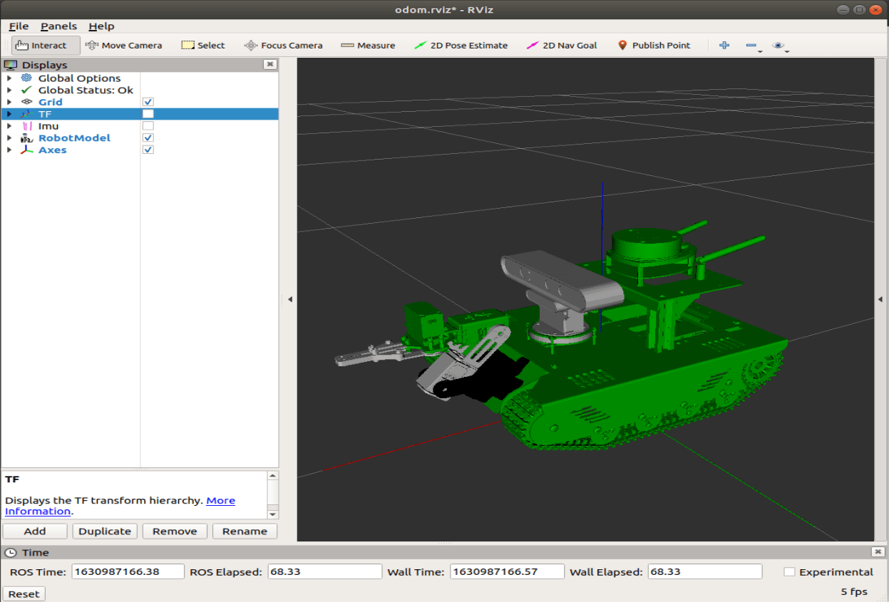
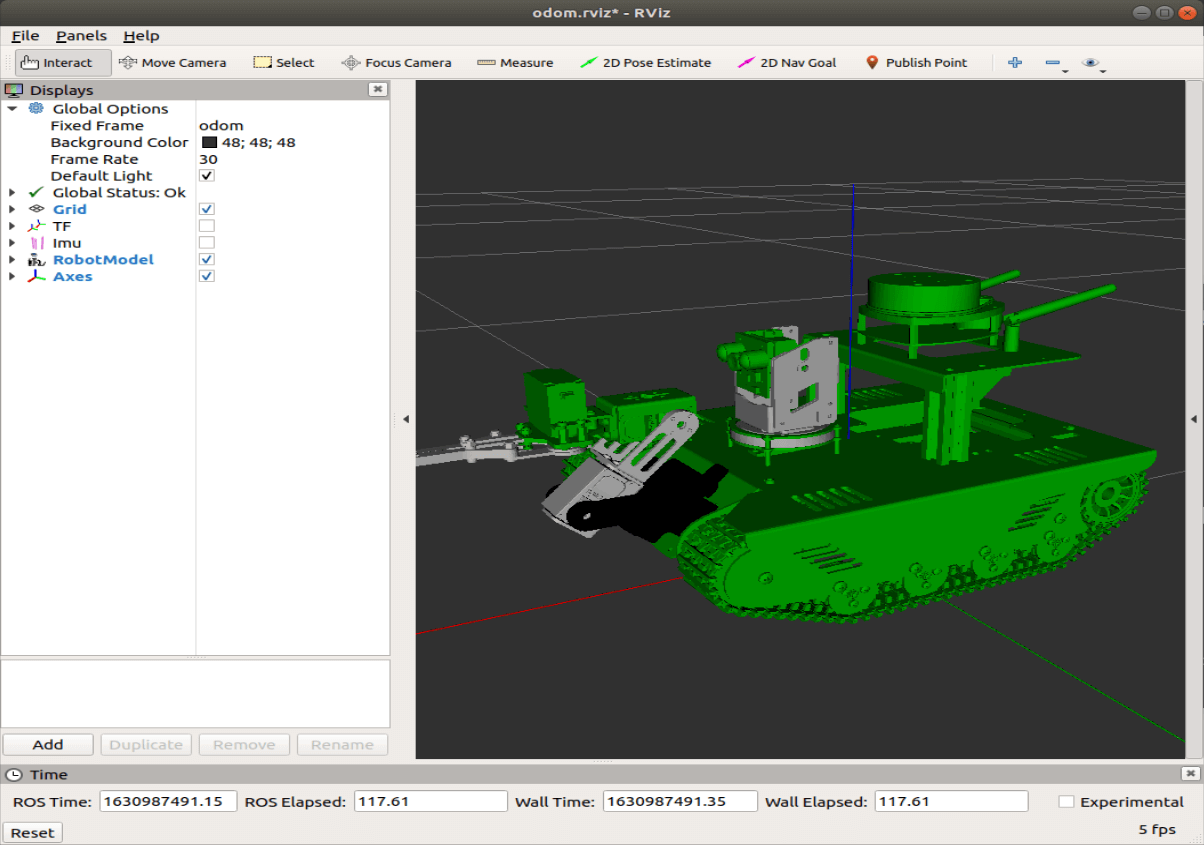
- rviz
xxxxxxxxxxroslaunch transbot_bringup view_odom.launch
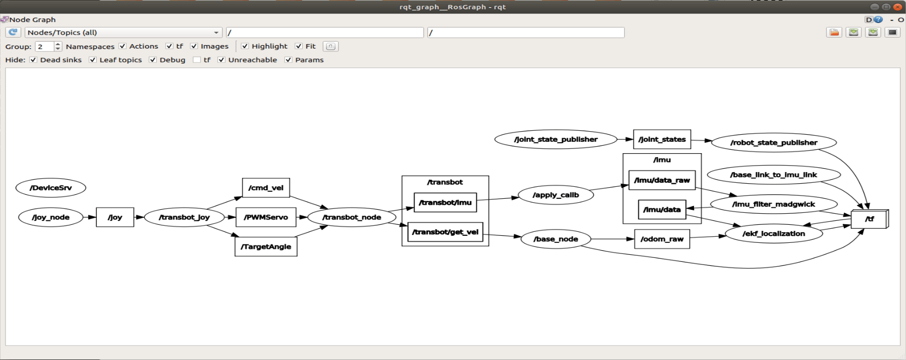
- View node graph
xxxxxxxxxxrqt_graph
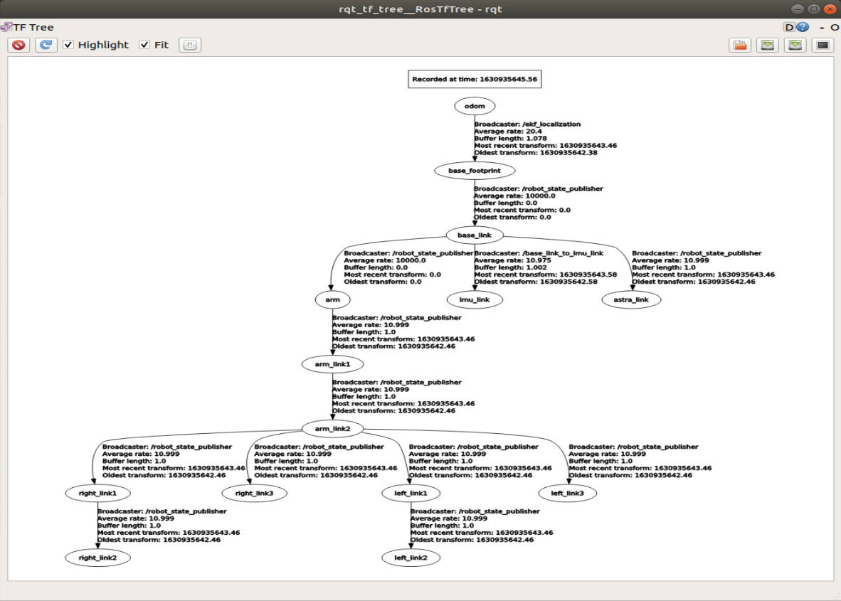
- tf tree
xxxxxxxxxxrosrun rqt_tf_tree rqt_tf_tree
5.2、Main node
5.2.1、transbot_node
| Topic | Type | Parsing |
|---|---|---|
| /transbot/imu | sensor_msgs/Imu | The most primitive imu data of the car |
| /transbot/get_vel | geometry_msgs/Twist | The most original odometer information of the car |
5.2.2、apply_calib
The IMU in Yahboom's image system has been calibrated. If you are using a Yahboom image file, no calibration is required.
This course is for reference.
1)Topic
| / | Topic name | Type | Parsing |
|---|---|---|---|
| Subscribed | /raw_imu | sensor_msgs/Imu | Original, uncalibrated IMU measurement |
| Published | /imu/data_raw | sensor_msgs/Imu | Corrected, calibrated IMU measurement value |
2)Parameter
| Parameter name | Type | Defaults value | Parsing |
|---|---|---|---|
| ~calib_file | string | "imu_calib.yaml" | Read calibration parameter file |
| ~calibrate_gyros | bool | true | Whether to calculate the deviation of the gyro and subtract the deviation when starting |
| ~gyro_calib_samples | int | 100 | Number of measurements used to calculate gyro deviation |
5.2.3、imu_filter_madgwick
1)Intrudction
IMU refers to a six-axis sensor, including gyroscope and accelerometer.
MARG refers to a nine-axis sensor, and a magnetometer is added to the IMU.
xxxxxxxxxxIMU = gyroscope + accelerometerMARG(Magnetic, Angular Rate, and Gravity) = gyroscope + accelerometer + magnetometer
2)Topic
| / | Topic name | Type | Parsing |
|---|---|---|---|
| Subscribed | /imu/data_raw | sensor_msgs/Imu | Message of the calibrated IMU data, including angular velocity and linear acceleration |
| Subscribed | /imu/mag | sensor_msgs/MagneticField | [Optional] Magnetometer, will be affected by magnetic field |
| Published | /imu/data | sensor_msgs/Imu | Fusion of Imu information. |
3)Parameter
| Parameter name | Type | Defaults | Parsing |
|---|---|---|---|
| ~gain | double | 0.1 | The gain of the filter. The higher the value, the faster the convergence speed, but the greater the noise. The lower the value, the slower the convergence speed, but the smoother the signal. Range: 0.0 to 1.0 |
| ~zeta | double | 0.0 | Gyro drift gain (about rad/s). Range: -1.0 to 1.0 |
| ~mag_bias_x | double | 0.0 | Magnetometer bias (hard iron correction), x component. Range: -10.0 to 10.0 |
| ~mag_bias_y | double | 0.0 | Magnetometer bias (hard iron correction), y component. Range: -10.0 to 10.0 |
| ~mag_bias_z | double | 0.0 | Magnetometer bias (hard iron correction), z component. Range: -10.0 to 10.0 |
| ~orientation_stddev | double | 0.0 | The standard deviation of the direction estimate. Range: 0.0 to 1.0 |
| ~world_frame | string | "nwu" | The world frame that indicates the direction. The old default value is "nwu" (northwest up). New deployments should use "enu". Valid values: "nwu", "enu", "ned". |
| ~use_mag | bool | true | Whether to use magnetic field data in data fusion. |
| ~use_magnetic_field_msg | bool | false | If set to true, subscribe to /imu and /mag topics as sensor_msgs/MagneticField; if set to false (it not recommended), use geometry_msgs/Vector3Stamped |
| ~fixed_frame | string | odom | The parent coordinate system to be used in publishing |
| ~publish_tf | bool | false | Whether to publish the TF transformation indicating the direction of the IMU, as the pose of the IMU; Use the fixed coordinate system as the parent coordinate system, and input the imu information as the child coordinate system |
| ~reverse_tf | bool | false | If set to true, the transformation from the imu coordinate system to the fixed coordinate system will be issued. |
| ~constant_dt | double | 0.0 | The dt to be used; if it is 0.0 (default value), the dynamic value of dt is calculated from the start of the message. |
| ~publish_debug_topics | bool | false | If set to true, two debugging topics are posted. |
| ~stateless | bool | false | If set to true, the filtered direction will not be published. Instead, stateless estimates of bearing are issued based only on the latest accelerometer (and optionally magnetometer) readings. Used for debugging. |
| ~remove_gravity_vector | bool | false | If set to true, the gravity vector is subtracted from the acceleration field in the published IMU message. |
5.2.4、robot_localization
1)Introduction
robot_localization is a collection of state estimation nodes. Each node is an implementation of a nonlinear state estimator for robots moving in 3D space. It includes two state estimation nodes ekf_localization_node and ukf_localization_node. In addition, robot_localization provides navsat_transform_node, which helps to integrate GPS data.
ekf_localization_node is an implementation of Extended Kalman Filter. It uses an omni-directional motion model to predict the state in time, and uses the sensor data to correct the estimated value of the prediction.
ukf_localization_node is an implementation of Unscented Kalman Filter. It uses a set of carefully selected sigma points to project the state through the same motion model used in EKF, and then uses these projected sigma points to recover the state estimation and covariance. This eliminates the use of the Jacobian matrix and makes the filter more stable. However, compared with ekf_localization_node, it is also more computationally cumbersome.
topic
| / | Topic | Type | Parsing |
|---|---|---|---|
| Subscribed | /imu/data | sensor_msgs/Imu | Filtered imu information |
| Subscribed | /odom_raw | nav_msgs/Odometry | Odometer information |
| Published | /odom | nav_msgs/Odometry | Converged odometer information |
| Published | /tf | tf2_msgs/TFMessage | Coordinate system information |
2)Parameter
frequency: the true frequency (in Hz) at which the filter generates the estimated state value. Note: The filter will only start calculation after it receives at least one message from one of the inputs.
[sensor]: For each sensor, the user needs to define this parameter according to the message type. The index of each parameter name starts from 0 (for example odom0, odom1, etc.) and must be defined in order (for example, if pose1 has not been defined, do not use pose0 and pose2). The value of each parameter is the topic name of the sensor.
xxxxxxxxxxodom0: /odom_rawimu0: /imu/data[sensor]_differential: For each of the above-defined sensor messages containing pose information, the user can specify whether the pose variables should be integrated differentially. If the given value is set to true, then for the measurement from the relevant sensor at time t, we will first subtract the measured value at time t-1, and then convert the resulting value to speed.
xxxxxxxxxx~odomN_differential~imuN_differential~poseN_differential[sensor]_relative: If this parameter is set to true, any measurement value from the sensor will be fused relative to the first measurement value received from the sensor. This is useful in the following situations, for example, if you want the state estimate to always start at (0,0,0), and the roll, pitch, and yaw angle values are (0,0,0).
xxxxxxxxxx~odomN_relative~imuN_relative~poseN_relativetwo_d_mode: If your robot is running in a flat environment and can ignore subtle changes in the ground (as reported by the IMU), set it to true. It merges all 3D variables (Z, roll, pitch and their respective speed and acceleration) into a value of 0. This ensures that the covariance of these values does not explode, and at the same time ensures that the state estimate of your robot is still fixed on the X-Y plane.
odom0_config:[ false, false, false, false, false, false, true, true, false, false, false, true, false, false, false ]
odom0_config: [false, false, false, false, false, false, true, true, false, false, false, true, false, false, false]
The order of Boolean values is: [[X], [Y], [Z], [roll], [pitch], [yaw], [X'], [Y '], [Z' ], [roll'] ,【Pitch'】,【yaw'】,【X''】,【Y''】,【Z''】,【roll''】,【pitch''】,【yaw''】]. The user must specify which variables of these messages should be incorporated into the final state estimate.
3)Transformation of release
If the user's world_frame parameter is set to the value of odom_frame, the conversion will be published from the coordinate system given by the odom_frame parameter to the coordinate system given by the base_link_frame parameter. If the user's world_frame parameter is set to the value of map_frame, the conversion will be published from the coordinate system given by the map_frame parameter to the coordinate system given by the odom_frame parameter.
For example, we set to publish the conversion from the coordinate system given by the [odom_frame] parameter to the coordinate system given by the [base_link_frame] parameter.
xxxxxxxxxxodom_frame: odombase_link_frame: base_footprintworld_frame: odom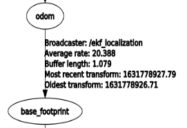
5.3、Precautions
While starting the robot, the robot is stationary. If the buzzer keeps ringing, there are two possibilities:
- The posture of the robot is (bias = [0.0, 0.0, 0.0]);
- The system detects that the robot is in free fall.
Solution:
- Close the terminal and restart the command;
- Close the terminal, press the PCB board reset button [RESET] and then restart the command.