5.1 Using of GPIO
Note: In the image operating system provided by Yahboom, the APP remote control process is enabled by default, in order to avoid multiple occupations of internal resources, causing some functions to fail to operate normally.
Before you running the code of this course, please follow the following to close the APP remote control process.
If you want to permanently close the function of the APP control process that starts automatically after booting, execute the following command:
sudo systemctl disable jetbotmini_start
If you want to permanently open the function of the APP control process that starts automatically after booting, execute the following command:
xxxxxxxxxxsudo systemctl enable jetbotmini_start
If you do not restart Jetbotmini to restart the APP control process function, execute the following command:
xxxxxxxxxxsudo systemctl stop jetbotmini_startsudo systemctl start jetbotmini_start
5.1.1 Introduction to GPIO port resources
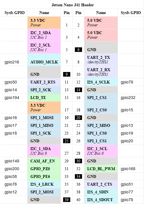
As shown in the figure below, it is the GPIO port table on the Jetson Nano of the main control board used by Jetbot Mini. Its GPIO port is the same as the Raspberry Pi interface. Its driver file and its usage method are all related to the Raspberry Pi GPIO port. similar.
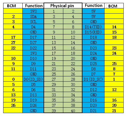
But when we program, the BCM code number is generally used, as shown in the following figure:
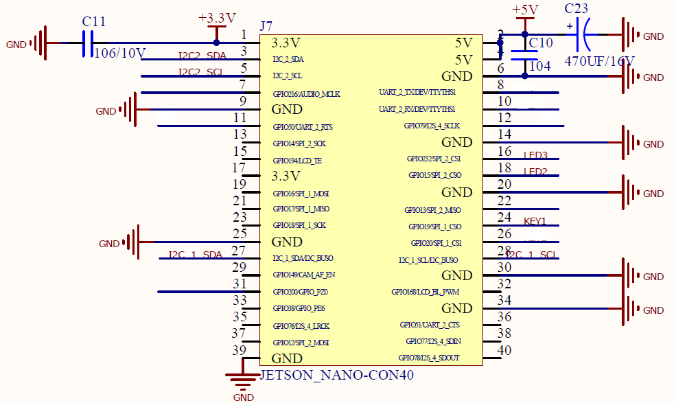
After reading the GPIO structure of Jetsonnano, then I will introduce to you the interface pin diagrams used in our Jetbotmini expansion board. From the Jetbotmini expansion board interface diagram, we will give an example of the relative applied pins as follows:
| Number of BCM | Function | Corresponding peripheral |
|---|---|---|
| 1、0 | I2C1: SCL、SDA | OLED |
| 3、2 | I2C2: SCL、SDA | Coprocessor |
| 24、23 | LED2、LED3 | Onboard Light |
| 8 | KEY | Button |
After reading the above introduction, now we should be able to understand the GPIO ports used and their corresponding functions, let's try to use them one by one!
If you are not using the Jetbotmini factory image provided by Yahboom, please confirm whether the relevant usage rights are enabled according to the operation in the section 3.4.1 Enable Peripheral Permissions before using GPIO.
5.1.2 Light up On board LED
As I said to you above, Jetson nano's GPIO port structure and the Raspberry Pi GPIO port driver can be shared. In the Jetson nano GPIO driver, define the called name as RPi.GPIO or Jetson.GPIO. Calling Jetson's GPIO port with RPi.GPIO or Jetson.GPIO can successfully call the GPIO driver.
We can see that the general steps to use the GPIO port to light up the LED light are:
1. Set GPIO port mode
2. Set GPIO output mode/input mode
3. Set the initial level of the GPIO port
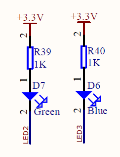
It can be seen from the schematic diagram that the GPIO port is turned on at a low level to light up the LED light. After executing the above code, we can see that the green onboard LED indicator will flip 4 times per second and blink 2 times per second.
The corresponding complete source code is located:
/home/jetson/Notebooks/English/3.Use_of_GPIO/1.Turn_on_the_LED/Turn_on_the_green_LED.ipynb
Among them, the code of [Turn_on_the_blue_LED] is the same except for the different GPIO ports that it drives. You can try to run it to see the phenomenon.
5.1.3 Use of buttons
Above we have used the GPIO port to operate the onboard LED indicator. The only difference between the use of the buttons on Jetbotmini is that the GPIO is set to input mode. Of course, if it is set to input mode, there is no starting point. One statement. Let's see the source code implementation process:
xxxxxxxxxximport RPi.GPIO as GPIOimport time# Pin Definitons:led_pin = 24 # BOARD pin 24 greenbut_pin = 8 # BOARD pin 8 key1def main(): prev_value = None # Pin Setup: GPIO.setmode(GPIO.BCM) # BCM GPIO.setup(led_pin, GPIO.OUT) # LED pin set as output GPIO.setup(but_pin, GPIO.IN) # Button pin set as input # Initial state for LEDs: GPIO.output(led_pin, GPIO.LOW) print("Starting demo now!") try: while True: curr_value = GPIO.input(but_pin) if curr_value != prev_value: GPIO.output(led_pin, not curr_value) prev_value = curr_value print("Outputting {} to Pin {}".format(curr_value, led_pin))# time.sleep(0.5) finally: GPIO.cleanup() # cleanup all GPIOif __name__ == '__main__': main()Here we use the LED we just learned to remind when monitoring key events, and use the on-board green LED to indicate the state of the key. When the key is pressed, the green LED indicator is extinguished, and when the pressed key is released , The green indicator light is lit. When a key event occurs, the current status will be printed at the bottom of the cell when the key is pressed and when the key is released. And will be below.
The corresponding complete source code is located:
/home/jetson/Notebooks/English/3.Use_of_GPIO/2.Use_of_keys/Use_of_keys.ipynb