How to use lidar
Note: The baud rate is different between A1/A2<115200>, A3/S1<256000> and S2<1000000>.
Note: The information of the lidar M2M2 and the radar of this course (A1/A2/A3/S1/S2) are different, please view the information according to the corresponding model
Note: "Slan Lidar Course" is based on the use of Transbot crawler vehicles, for reference only! ! !
How to use lidar1、Overview2、Silan lidar components2.1、Laser2.2、Receiver2.3、Signal processing unit2.4、Rotating mechanism3、Principle of single-line lidar3.1、Triangular Ranging Method3.1.1、Direct shot3.1.2、Oblique shot3.2、TOF Ranging Method4、Lidar parameter comparison5、Application scenarios6、Run rplidar node6.1、Build the rplidar ros package6.2、Remap the USB serial port6.3、Run rplidar ros package7、RoboStudio test7.1、Install7.2、View device7.3、Log in7.4、Connect7.5、Test8、frame_grabber8.1、View device8.2、connect8.3、Start up
Lidar technology support Email :support@slamtec.com
Lidar wiki:http://wiki.ros.org/rplidar
Lidar SDK:https://github.com/Slamtec/rplidar_sdk
Lidar ROS:https://github.com/Slamtec/rplidar_ros
Lidar tutorials:https://github.com/robopeak/rplidar_ros/wiki
Lidar website:http://www.slamtec.com/cn/Support
Test the PC computer:https://www.slamtec.com/cn/RoboStudio
1、Overview
Single-line lidar refers to a single-line laser beam emitted by the laser source. It is divided into triangular ranging and TOF lidar. It is mainly used in the field of robotics.
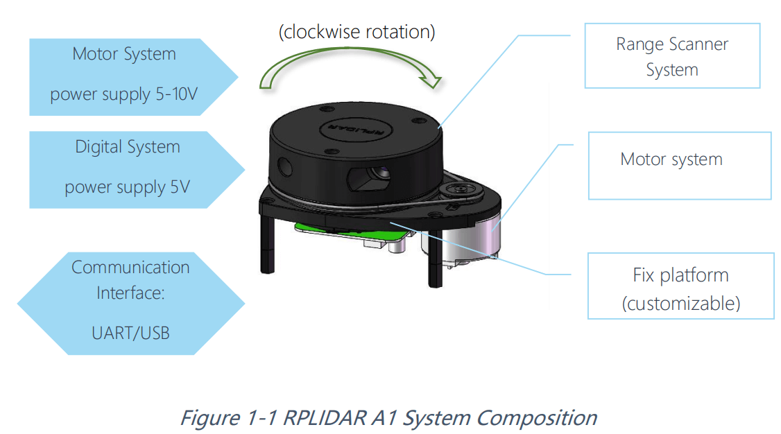
2、Silan lidar components
Take SLAMTec lidar as an example, which is mainly composed of 4 core components: laser, receiver, signal processing unit and rotating mechanism.
2.1、Laser
The laser is the laser emitting mechanism in the lidar. During work, it will light up in pulses.
The RPLIDAR A3 series lidar of SLAMTec will turn on and off 16000 times per second.
2.2、Receiver
After the laser emitted by the laser hits the obstacle, the reflected light will be converged on the receiver through the lens group through the reflection of the obstacle.
2.3、Signal processing unit
The signal processing unit is responsible for controlling the emission of the laser and processing the signal received by the receiver.
Based on this information, the distance information of the target object is calculated.
2.4、Rotating mechanism
The above three components constitute the core part of the measurement.
The rotating mechanism is responsible for rotating the above-mentioned core components at a stable speed, so as to realize the scanning of the plane and generate real-time plan information.
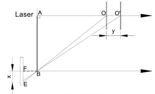
3、Principle of single-line lidar
The working principle of the radar is shown in the figure below:
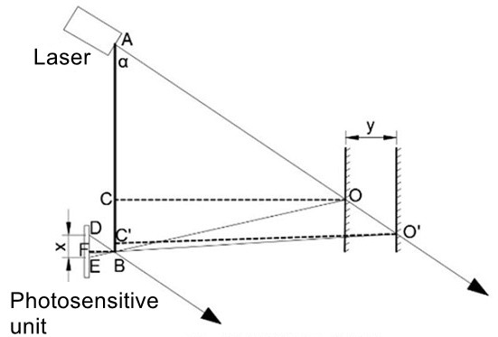
3.1、Triangular Ranging Method
3.1.1、Direct shot
3.1.2、Oblique shot
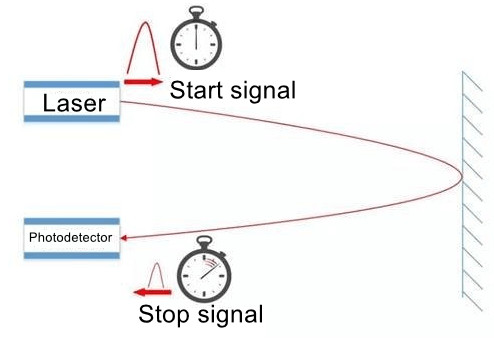
3.2、TOF Ranging Method
4、Lidar parameter comparison
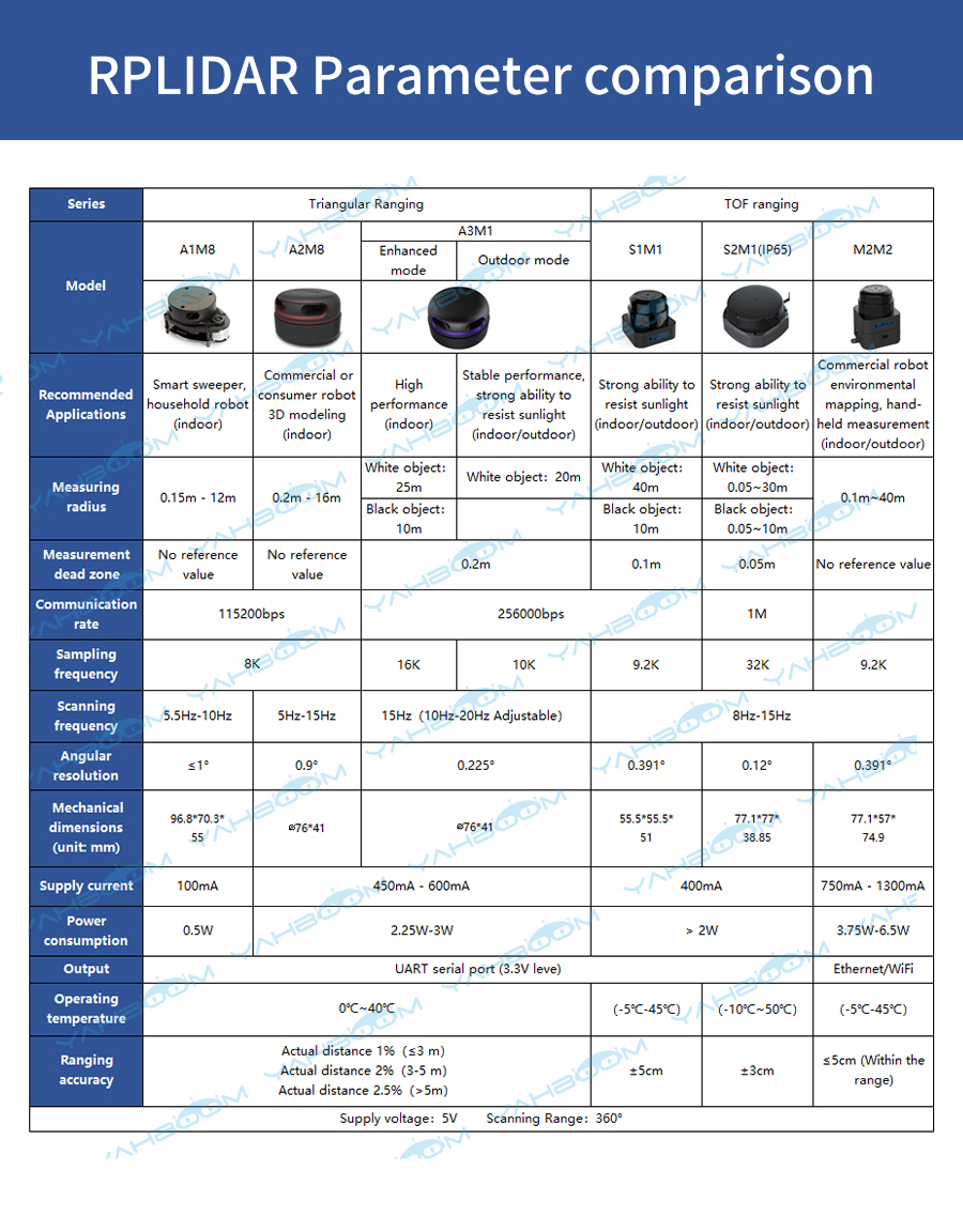
It can be seen from the figure above that parameters such as measurement radius, sampling speed, scanning frequency, and angular resolution are important indicators of radar performance.
| Performance | Description |
|---|---|
| Ranging radius | Radar measurement range |
| Ranging sampling rate | How many ranging outputs are performed in one second |
| Scanning frequency | How many scans the radar does in one second |
| Angular resolution | Angular steps of two adjacent ranging |
| Measurement resolution/accuracy | Can perceive the minimum distance change |
5、Application scenarios
Lidar plays an indispensable role in many fields such as autonomous robot positioning and navigation, spatial environment mapping, and security.
6、Run rplidar node
6.1、Build the rplidar ros package
Function download link:https://github.com/Slamtec/rplidar_ros/
Clone this feature pack to your workspace src folder
Run catkin_make to build rplidarNode and rplidarNodeClient
Note: If you do not write the update environment variable to【.bahsrc】, you must update the environment variable before each execution of the running program.
source devel/setup.bash # Update environment variables6.2、Remap the USB serial port
Under the path of rplidar_ros function package, install USB port remapping:
xxxxxxxxxx./scripts/create_udev_rules.sh
Use the following command to modify the remapping:
xxxxxxxxxxls -l /dev | grep ttyUSB

After changing the USB port and remapping, change the startup file related to the serial_port value.
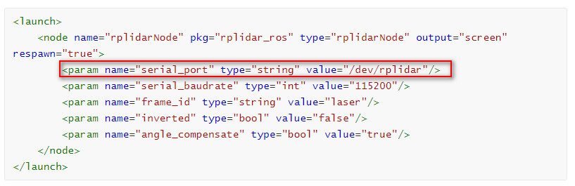
6.3、Run rplidar ros package
- Method 1
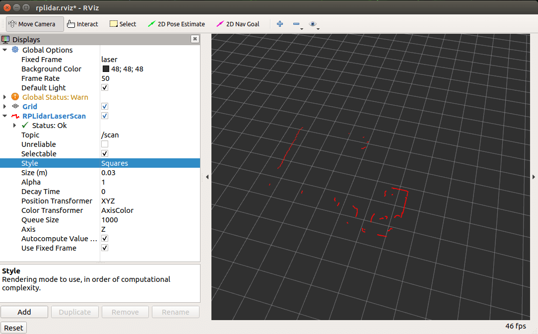
Run rplidar node, view in rviz
xxxxxxxxxxroslaunch rplidar_ros view_rplidar.launch # RPLIDAR A1/A2roslaunch rplidar_ros view_rplidar_a3.launch # RPLIDAR A3roslaunch rplidar_ros view_rplidar_s1.launch # RPLIDAR S1roslaunch rplidar_ros view_rplidar_s2.launch # RPLIDAR S2You can see rplidar scan results in rviz.
- Method 2
Run rplidar node
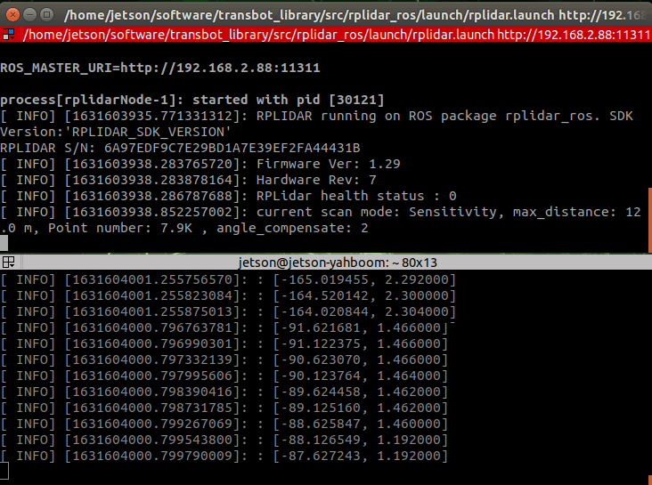
xxxxxxxxxxroslaunch rplidar_ros rplidar.launch # RPLIDAR A1/A2roslaunch rplidar_ros rplidar_a3.launch # RPLIDAR A3roslaunch rplidar_ros rplidar_s1.launch # RPLIDAR S1roslaunch rplidar_ros rplidar_s2.launch # RPLIDAR S2Start the test application
xxxxxxxxxxrosrun rplidar_ros rplidarNodeClient
You should see rplidar scan results in the console
7、RoboStudio test
Test tool download link:https://www.slamtec.com/cn/RoboStudio
Take S1M1 radar as an example, other models are similar.
7.1、Install
Double-click robostudio icon to install, and continue to the next step until the installation is complete. Adjust the radar to the corresponding baud rate [A1/A2: 115200, A3/S1: 256000, S2: 1000000].
Using the original data cable to connect the device (for example: PC).
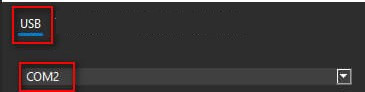
7.2、View device
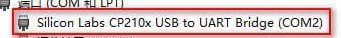
由上图可知道,激光雷达的端口是【COM2】。
7.3、Log in
Log in for the first time, you need to register before you can use it. Select [Radar], right-click in the blank area of the radar bar, and select [Manually connect to radar...].
7.4、Connect
Select the corresponding [COM2], and click [Connect].
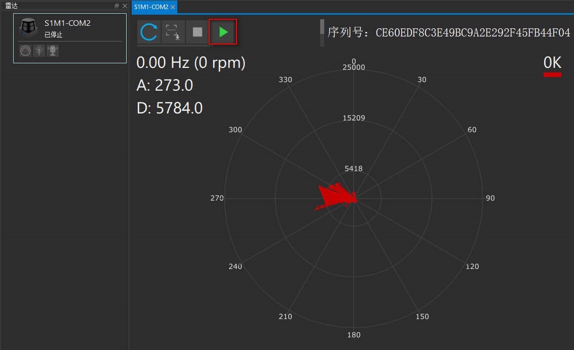
7.5、Test
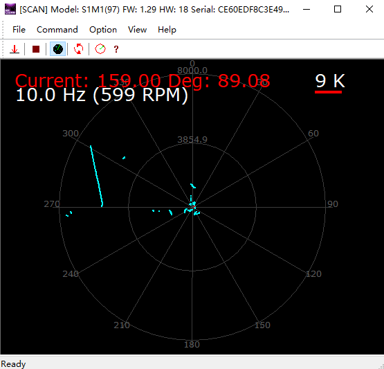
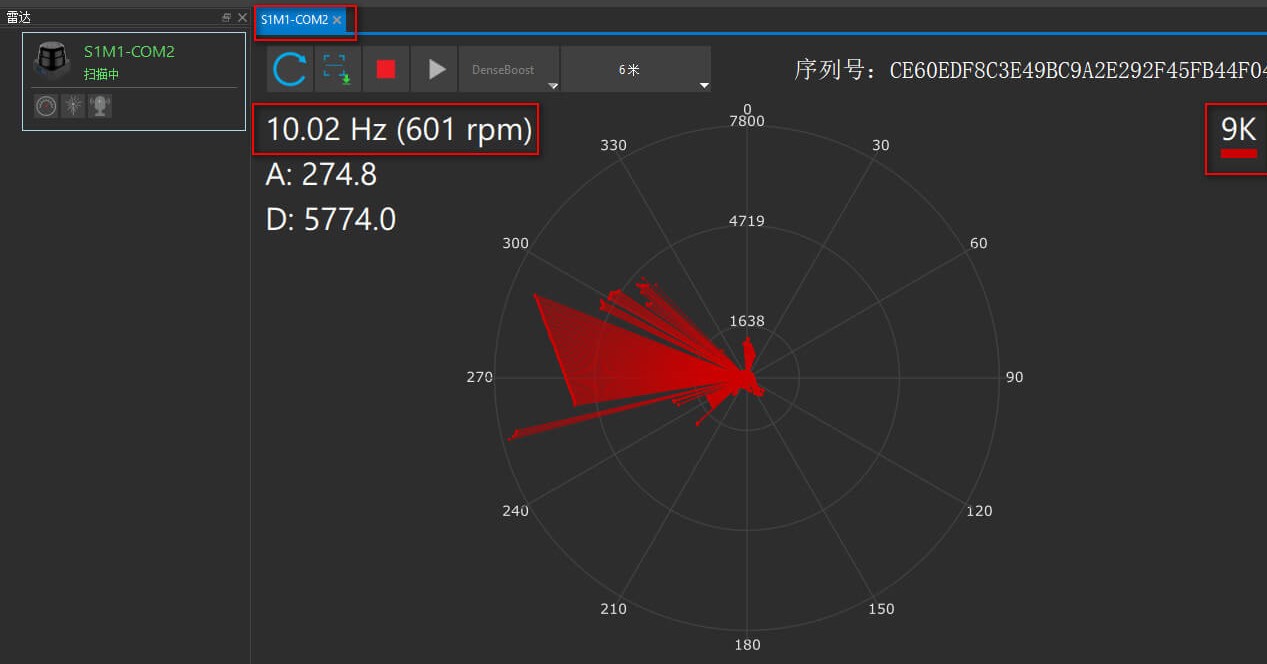
Enter the test interface, click the green triangle to start the lidar test.
We can view the basic information of the radar: model [S1M1], sampling frequency [9K], scanning frequency [10.02Hz], etc.
8、frame_grabber
8.1、View device
The operation is the same as in 7.2.
8.2、connect
Select the corresponding port [COM2] and baud rate [256000], and click [OK].

8.3、Start up
Click as shown in the figure below to activate the button.
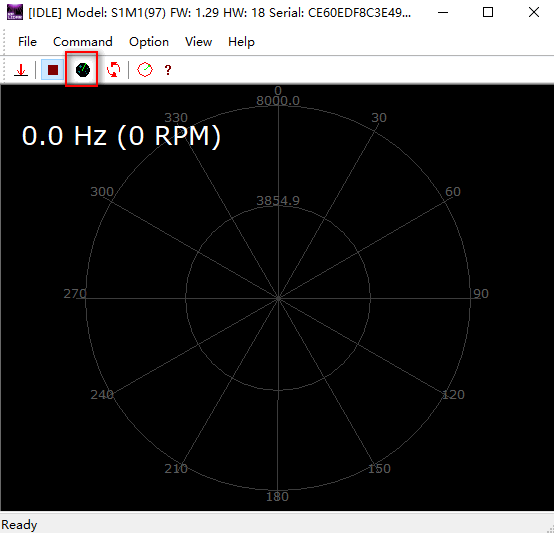
The effect diagram is as follows.